
Surfaces Applications
Examples of each button's functionality can be viewed by clicking on the button.Creates a ruled surface between the selected curves. If more than two curves are selected, a ruled surface is created between each pair of curves in the order they were selected. SolidMesh tries to determine the proper orientation of the curves to prevent twisting. The Reverse toggle is a "manual override" of that orientation. If the Reverse toggle is turned on, then the surface will be constructed to twist.Create Swept surface
To create a swept surface, select any number of curves and then select the Create swept surface button. The first curve defines the sweep path (directorix) and the remaining curves define the cross-section. If the Orthogonal toggle is selected, the cross-section remains orthogonal to the sweep path. The direction of the sweep is along the directorix. The Reverse toggle can be used to switch the direction of the sweep path. To determine the direction of a curve, create a tangent vector at any point along the interior of the curve.Reverse toggle
The reverse toggle is used to switch the construction orientation of a ruled surface and to switch the orientation of the sweep path for a swept surface.Orthogonal toggle
The orthogonal toggle is used to enforce that the cross-section curve remains orthogonal to the sweep curve along the sweep path.Create Blended Swept surface
To create a blended swept surface, select three curves and then select the Create blended swept surface button. The first curve defines the sweep path (directorix) and the remaining two curves define the cross-section and must be on opposite ends of the directorix. If the Orthogonal toggle is selected, the cross-section remains orthogonal to the sweep path. The direction of the sweep is along the directorix. The Reverse toggle can be used to switch the orientation of the cross-section curves.If the surface is orthogonal and the directorix is a helix, a vector must be specified to define the direction of travel for the helix in order to prevent twisting.
Create transfinite interpolation (TFI) surface
To create a transfinite interpolation, pick four curves and then select the Create transfinite interpolation button. The result will be the generation of a TFI surface defined by the four picked curves. NOTE: The four curves must be geometrically adjacent (much higher tolerance than topologically adjacent) to create a TFI surface. If you cannot create the TFI surface due to the curve end points not matching, you will have to use the Snap button to repair any curves that are not within the geometric tolerance.Create degenerate TFI surface
To create a degenerate TFI surface, first pick three curves and a point, then select the Create degenerate TFI surface button. The result will be a degenerate TFI surface defined by three picked curves, representing three of the defining boundaries of the TFI surface, and a single picked point, representing a degenerate boundary. NOTE: The three curves and single point must be geometrically adjacent (much higher tolerance than topologically adjacent) to create a TFI surface. If you cannot create the TFI surface due to the curve end points not matching, you will have to use the Snap button to repair any curves that are not within the geometric tolerance.Create four-corner surface
To generate a linear surface with four corners, pick the four points which will define the corners, and then select the Create four-corner surface button to create the surface.Create plane
Creates a plane depending on the inputs provided:
- If three points are selected, the plane defined by those three points is created.
- If a point and a vector are selected, a plane is created at the chosen point. The plane will be normal to the picked vector.
- If only a point is selected, a plane is created in the same manner as above; but the vector fields, VX, VY, and VZ, are used in place of a selected vector.
Lofted surface
To generate a C2 splined surface (one which is continuous through the second derivative), pick at least three curves and the Lofted surface button. The number of control points is determined by the number of curves picked and the maximum display resolution of all of the curves. The minimum display resolution allowed is 3.Average surfaces
To create a surface which is the average of two or more surfaces, pick the surfaces and then select the Average surfaces button. The result will be the generation of the new average surface.Blend surfaces
To generate a cubic surface connecting two surfaces at their closest edges, pick the two surfaces and then select the Blend surfaces button. The closest edges of the two surfaces are determined automatically; however, picking the two desired edges overrides the automatic closest edge detection.Create surface of revolution
To generate a surface of revolution you must pick any number of curves, specify an axis of revolution [pick a point or specify a point in the X, Y, and Z fields and pick a vector or specify a vector using the vector fields], and click the Create surface of revolution button. For each curve picked, a surface of revolution is created about the axis of revolution starting from the value of the start angle field to the value of the end angle field (in degrees). The current location of a picked curve is defined to be at zero degrees and all rotations are relative to this position. The surface will be generated into an equal number of parts, which will be indicated by the number in the pieces field.Start angle field
The start angle field is used to specify the starting angle when a surface of revolution is being created. Values are in degrees.End angle field
The end angle field is used to specify the ending angle when a surface of revolution is being created. Values are in degrees.Pieces
The pieces field is only used along with the start and end angle fields. This field specifies the number of pieces in which the surface of revolution is created.Blended Revolve toggle
To create a blended surface of revolution, select two curves and specify the axis of revolution [pick a point or specify a point in the X, Y, and Z fields and pick a vector or specify a vector using the vector fields]. A blended surface will be created (using right-hand rule) running from the first curve selected to the second curve selected. Two surfaces will be created if the angle between the curves is between 90 and 180 degrees and three surfaces will be created if the angle is greater than 180 degrees.Create extruded surface
To create an extruded surface you must pick any number of curves and a vector to specify extrusion direction and then select the Create extruded surface button. For each curve picked, an extruded surface will be created in the specified direction. The extrusion distance is set by the distance field.Create offset surface
To create a surface which is the offset of another, pick the surface to be offset and then select the Create offset surface button. The new surface created is the set of all points at a certain distance from the picked surface in the direction of the set of all vectors normal to the picked surface. The distance is set by the distance field.Extend surface
To extend a surface from a certain edge, pick the surface and the edge from which to extend. You may then select the Extend surface button to create the extended surface. The surface will be extended by the distance specified in the distance field.Distance field
Surfaces are extruded, offset, and extended the distance that is indicated in the field.Create carpet patch
This function creates a "TFI" type surface using the same boundary input as a regular TFI, degenerate TFI or a Ruled surface. The carpet creates a C2-cubic spline surface with a user defined resolution. A carpet can also have boundary input of three curves and a point.The carpet will be projected onto any number of selected surfaces. The resulting projected "carpet patch" is a new surface which retains the boundaries but now lies on (or near) the selected surfaces. This utility is useful when a new surface is needed to close gaps in existing geometry. This can also be used to approximate surfaces (a crude form of data reduction) by selecting any number of NURBS surfaces(not trimmed, discrete, or CAPRI). All original input surfaces remain selected.
Resolution field
Used to specify the number of control points when creating carpet surfaces. The value in the Long Res field is applied to the side with the longest arc length, and the Short Res is applied to the side with the shortest arc length. CAUTION: The total number of control points created is the product of the two values specified.Project curves toggle
If this toggle is highlighted, the picked curves will be projected onto the picked surfaces prior to generating the carpet patch.Surface Macros Toggle
Use this toggle to go to the Surface Macros PaneSurface Macros Pane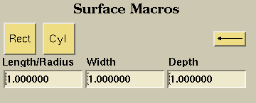
Rectangle Button
This button creates a Rectangular Prism with corner of origination being the selected point or the point defined by the value in XYZ Fields. For example, if the origin is {0,0,0} and the values in the "Length/Radius" "Width" and "Depth" are all 1 then the result would be a unit cube with a point being the origin and the opposite point diagonally would be {1,1,1}. The "Length/Radius" field corresponds to the length in the positive x direction. The "Width" field corresponds to the length in the positive y direction. The "Depth" field corresponds to the length in the positive z direction.Cylinder Button
This button creates a Cylinder with origin defined by the selected point or the point defined by the value in XYZ Fields. For example, if the origin is {0,0,0} and the values in the "Length/Radius" and "Depth" are all 1 (the value in "Width" is ignored) then the result would be a cylider with the two end circles having a center at the defined origin plus the value in "Depth" in the positive z direction.