AFLR43 Example Cases
Data files for a few AFLR43 sample cases are provided. Package archives
with all of the example cases are provided in aflr43-examples.tar.gz
(tar-gzip archive for Linux/MacOSX) and aflr43-examples.zip
(zip archive for Windows). Copy the package archive files and unpackage them in
a location of your choosing to run the example cases. All cases require minimal
resources. AFLR43 takes the provided input geometry definition and
automatically generates a surface and volume mesh with spacings based on
surface type, surface curvature and proximity of multiple components. AFLR43
as provided can work with a discrete geometry definition or an EGADS CAD
geometry definition.
AFLR43 command
line options include both parameter options for AFLR4 and AFLR3
components.
aflr43 [aflr4_param_options] [-AFLR3 aflr3_param_options]
The -AFLR3 flag is required to
separate the AFLR4 and AFLR3 options. In command line mode the AFLR4
input geometry definition file and the AFLR3 output mesh file names must
be specified. If the input geometry definition is an EGADS geometry
definition Model, then a tessellation of the AFLR3 output mesh is
included in the output EGADS geometry definition Model.
See
the AFLR43 documentation
for information on all available options
and usage. Alternatively, you can view text-based documentation at the
command line with the following command.
aflr43 -h or aflr43 -help
See the AFLR4
documentation and AFLR3 documentation for related information.
An overview of AFLR43
example cases is provided in the following along with run parameters. All
these cases use EGADS geometry definition Models and are also included
with AFLR4 sample cases. One uses Effective Bodies to aggregate multiple
Faces as Effective Faces. The other two cases use Face Topology that have Edges
that are internal to the given Face. AFLR3 will preserve these internal
Edges, which is particularly important when those Faces intersect BL regions
and are re-meshed within AFLR3. For each case the command line for AFLR43
along with equivalent for running AFLR4 and AFLR3 separately.
Either approach results in the exact same final output, and one should use
whichever is works with their overall process. Note that AFLR3 will only
produce an EGADS geometry definition Model with an output mesh tessellation
if the surface mesh was generated by AFLR4. Also, to run AFLR4
and AFLR3 separately you must use the aflr3t executable (not the base
aflr3 executable). In addition, note that in the separate process only the SURF
and UGRID file types retain the grid BCs. If another output file type is used (i.e.,
MESH) the aflr3t command line the same grid BC parameters as for aflr4 must be
added.
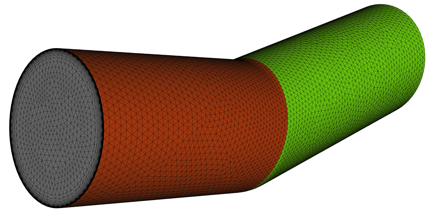
Bent Pipe with Effective
Topology.
A simple bent pipe with inflow and output ends. The underlying Model topology
with multiple Faces that have connectivity that produces artifacts in the surface
mesh. Reference length is set equal to the pipe diameter.
aflr43 -i bent_pipe_eff.egads -log -bl_ids 1,2 -int_ids 3,4
-AFLR3 -o a43_bent_pipe_eff.meshb
-bl -blds 0.01
aflr4 -i bent_pipe_eff.egads -log -bl_ids 1,2 -int_ids 3,4 -o
a4_bent_pipe_eff.surf
aflr3t -i
a4_bent_pipe_eff.surf -o a3_bent_pipe_eff.meshb -log -bl
-blds 0.01

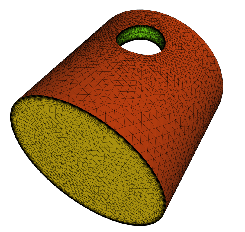
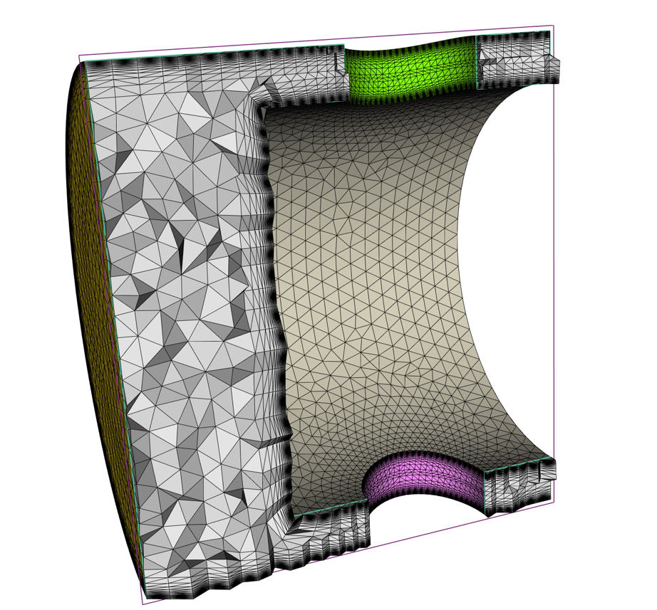
Piston.
A simple piston with inflow and outflow passages on both ends and the side
holes. Reference length is set equal to the minimum bounding box size of the
piston. Both holes and the piston surfaces have internal edges that are
preserved in the output volume mesh.
aflr43 -i piston.egads -log -bl_ids 1,6,7 -bl_ints 2,3,4,5
-AFLR3 -o a43_piston.meshb
-bl -blds 0.1
aflr4 -i piston.egads
-log -bl_ids 1,6,7 -bl_ints
2,3,4,5 - o a4_piston.surf
aflr3t -i
a4_piston.surf -o a3_piston.meshb -log -bl -blds 0.1
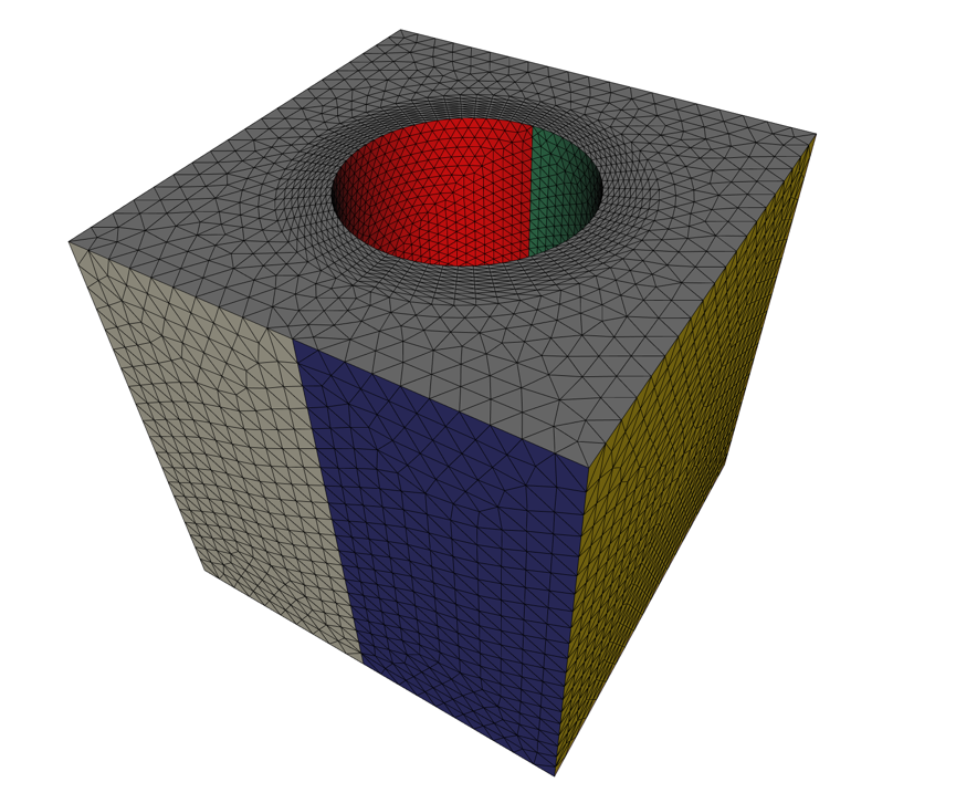
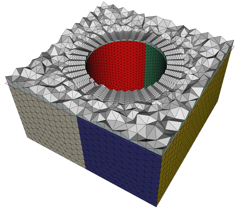
Box
with Cylinder
A simple box with a cylinder intersecting the inflow/outflow top and bottom.
Reference length is set equal to cylinder diameter. The top and bottom surfaces
have internal edges that are preserved in the output volume mesh. Note that body
1 (a farfield box) is ignored. Both box and cylinder surfaces have internal
edges that are preserved in the output volume mesh.
aflr43 -i mel.egads -log -std_ids 1,2,4,6,7 -bl_ids 8,9 -int_ids 3,5 -keep_bodies 0, -ref_len 0.1
-AFLR3 -o a43_mel.meshb
-bl -blds 0.01
aflr4 -i mel.egads
-log -std_ids 1,2,4,6,7 -bl_ids
8,9 -int_ids 3,5 -keep_bodies
0, -ref_len 0.1
-o a4_mel.surf
aflr3t -i
a4_mel.surf -o a3_mel.meshb -log -bl -blds 0.01