| 1.
Read the file periodic.igs.gz in with gluing and trimming enabled. This is half of a rotary configuration. What is needed is to make the entrance and exit into periodic surfaces so the rotary simulation can be performed.
|

|
| 2.
Periodic surfaces are created in pairs. The pair of surfaces in this example are the two selected faces. For the surfaces to periodic, they need to be their own group. Select each surface individually and put them in their own group.
|

|
| 3. .
Verify that they are in their own group by noticing that they are different colors now. There should be five groups in total now.
|

|
| 4.
In order to assign the periodic condition to a surface, it has to be paired with another surface. Special attention must be paid to the pairing process so that the desired results are obtained. The order in which surfaces and points are picked is essential. To pair the two end surfaces, first pick the surface on the left.
|

|
| 5.
Then, pick the surface on the right.
|

|
| 6.
Next, pick an interior point on the surface on the left. For this example it is the left-most point on the LowerInnerTube.
|
|
7.
Finally, pick the right-most point on the LowerInnterTube. Your screen should look identical (at least the picked geometry) to the one above. Once all that is done, toggle  and press and press  . The order of picking the surfaces first and then the points is just for example. The order of the individual type of picked entities is what is important. For example, you could have picked the left surface, then left point, the right surface, and finally the right point and arrived at the same result. . The order of picking the surfaces first and then the points is just for example. The order of the individual type of picked entities is what is important. For example, you could have picked the left surface, then left point, the right surface, and finally the right point and arrived at the same result.
|
|
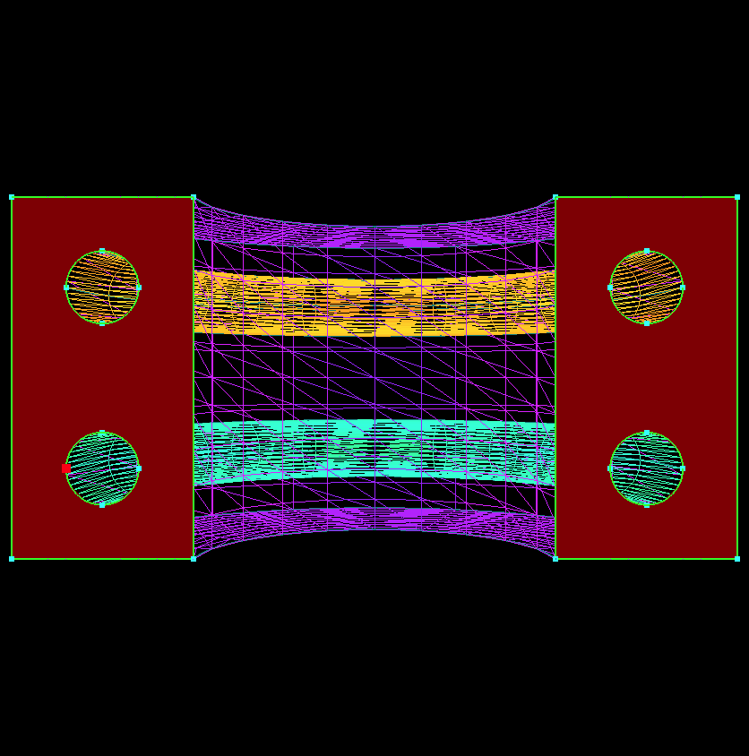
| 8.
Once the surfaces are set as Periodic, generate a surface grid with the suppled point spacings. The CAD geometry has been turned off and the surface grid has been displayed as a shaded wire frame so that the periodicity of the surface grids can be seen. If you look closely at the two end caps, they are identical-in that they are mirrors of each other. Technically speaking they are identical and have been translated and rotated during the transformation to arrive at the mirrored result.
|

|
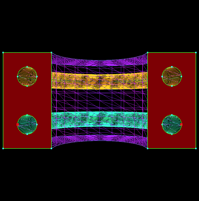
| 9.
If the periodic boundary condition is removed by un-toggling and pressing , and the surface grid was regenerated, the result would be similar but not exact. A good way to demonstrate this is to increase the surface resolution (lower the point spacing) so that more interior points are calculated during the grid generation. The figure to the right can be seen in the report and highlights how the surface differ slightly. The red edges are where the surface differs.
|
 |