AFLR4 Example Cases
Data files for a few AFLR4 sample cases are provided. Package archives
with all of the example cases are provided in aflr4-examples.tar.gz
(tar-gzip archive for Linux/MacOSX) and aflr4-examples.zip
(zip archive for Windows). Additional small test cases of trivial geometry that
can be used for debugging type work are provided in aflr4_caps-examples.tar.gz
(tar-gzip archive for Linux/MacOSX) and aflr4_caps-examples.zip
(zip archive for Windows). Copy the package archive files and unpackage them in
a location of your choosing to run the example cases. All cases require minimal
resources. AFLR4 takes the provided input geometry definition and
automatically generates a surface mesh with spacings based on surface type,
surface curvature and proximity of multiple components. AFLR4 as
provided is capable of working with a discrete geometry definition or an EGADS
CAD geometry definition.
CAD functionality within AFLR4
uses the Engineering Geometry Aircraft Design System (EGADS) from MIT
and Open CASCADE from Open CASCADE S.A.S. for. Both EGADS and Open
CASCADE are freely available as part of the Engineering Sketch Pad (ESP)
and licensed under The GNU Lesser General Public License, version 2.1. EGADS
and Open CASCADE libraries are required only to use the CAD geometry
capability integrated in AFLR4. All AFLR4 package files include
the required libraries and headers. Source code and pre-built binaries of ESP
with EGADS and Open CASCADE components are available at MIT’s
Engineering Sketch Pad software distribution site.
Common AFLR4 options are listed below.
|
aflr4 |
[options] |
|
|
|
-i input_file |
input file |
|
|
-o output_file |
output file |
|
|
-log |
generate a log file |
|
|
-ff_ids list_of_farfield_IDs |
farfield surface IDs - if applicable |
|
|
-int_ids list_of_BL_intersecting_IDs |
BL intersecting surface IDs (eg.
symmetry plane) - if applicable |
|
|
-ref_len reference_length |
should be physically based, e.g. chord length |
|
|
-er_all |
use edge refinement based on surface to surface
discontinuity on all surfaces |
|
|
-np number_of_processes |
run in parallel with specified number of processes |
|
|
-min_ncell 1 |
reduce number of isotropic cells to one between BL regions
- if applicable |
|
|
-BL_thickness BL_thickness |
BL thickness - if applicable |
|
|
or |
|
|
|
-Re_l Reynolds Number |
Reynolds Number based on reference length for estimating
BL thickness |
Note that the -BL_thickness,
-Re_l, and -min_ncell
options are only used during proximity checking between different bodies/components.
Note that AFLR4 outputs a rerun argument file named case_name.aflr4.arg which
contains all pertinent options. To rerun with the rerun argument file simply
run aflr4 case_name.aflr4.arg.
See
the AFLR4 documentation
for information on all available options and usage. Alternatively, you can
view text-based documentation at the command line with the following command.
aflr4 -h or aflr4 -help
An overview of AFLR4 example cases is provided in the following
along with run parameters.
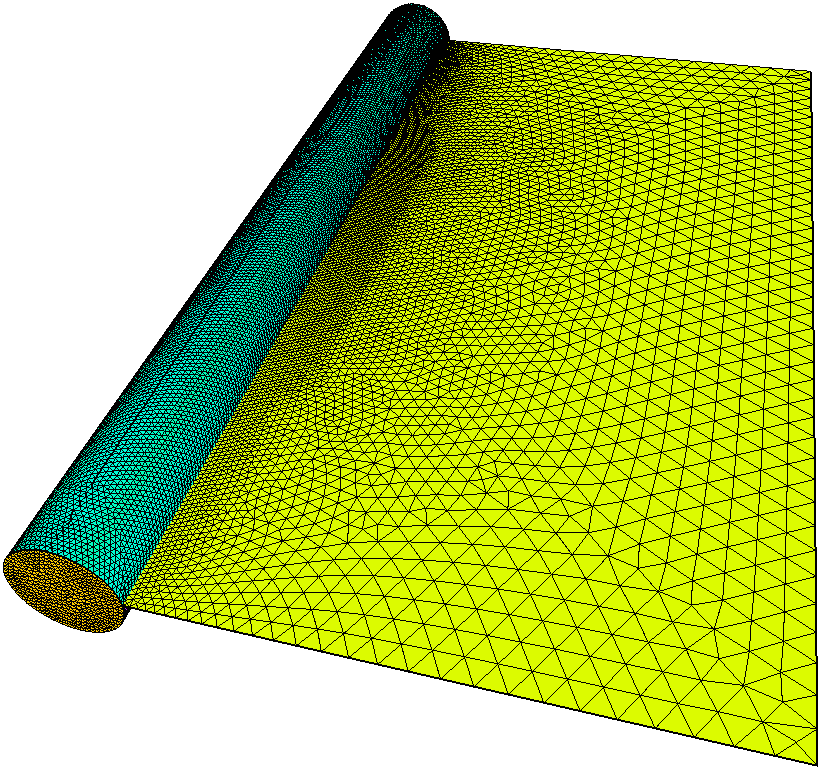
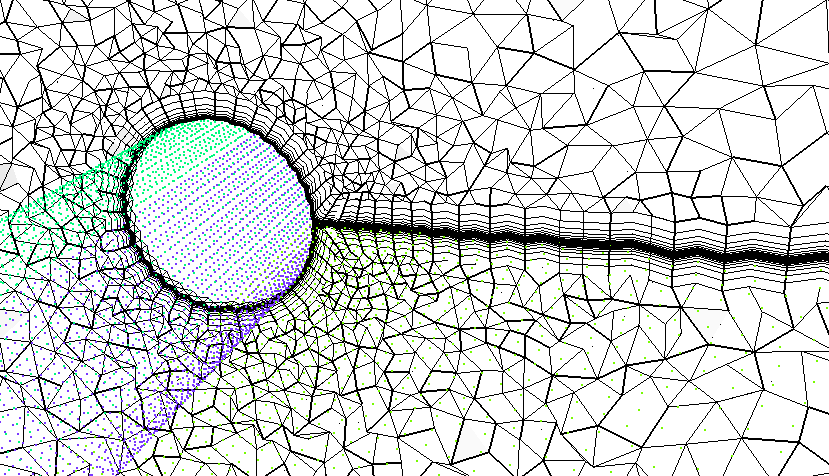
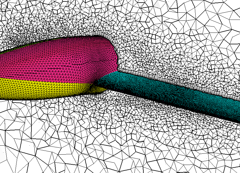
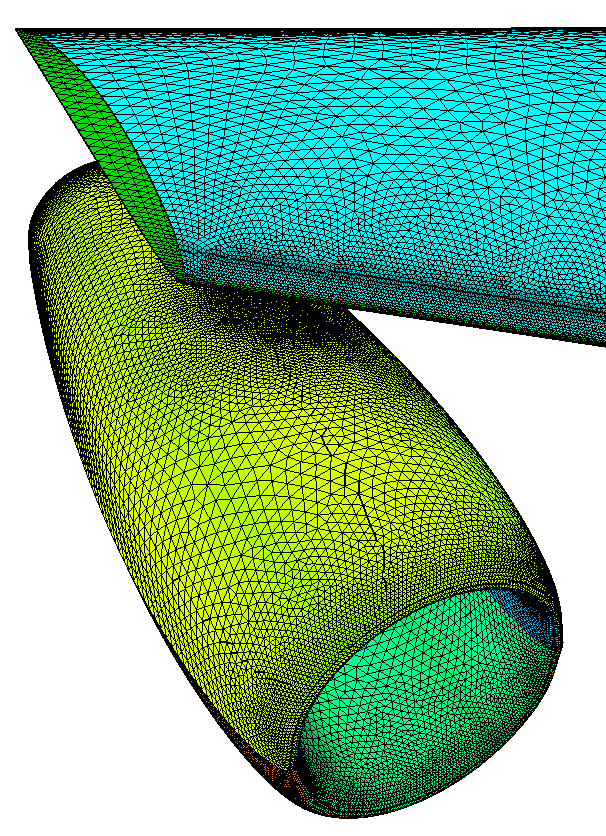
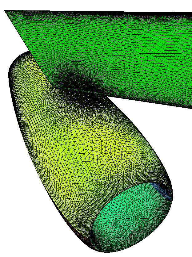
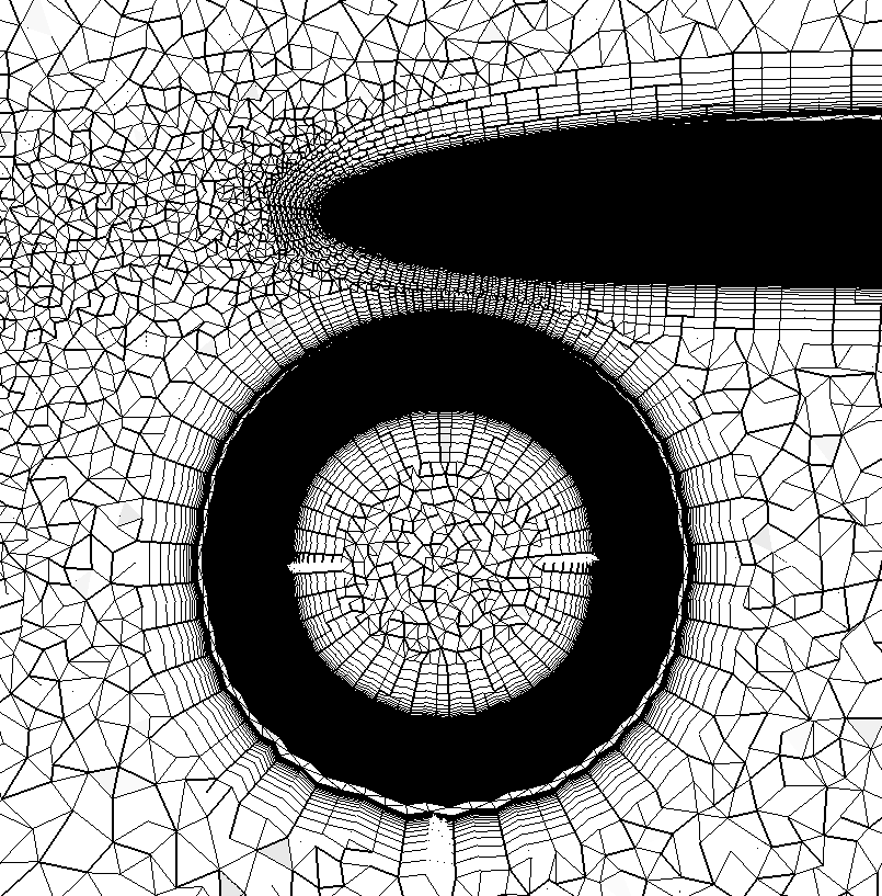
Cylinder & Wake Sheet
(CAD geometry definition).
A simple cylinder and transparent wake sheet with non-manifold connection.
Reference length is set equal to the cylinder diameter.
aflr4 -i cylinder_wake
-o cylinder_wake_new.surf
-log -ff_ids 6-11 -trnsp_bl_ids
5, ref_len=0.2 -log
A compatible volume mesh can be generated using AFLR3.
aflr3 -i cylinder_wake_new
-blc -blds 0.0001 -log
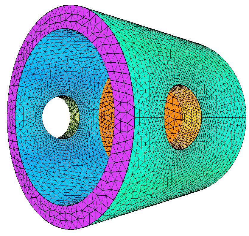
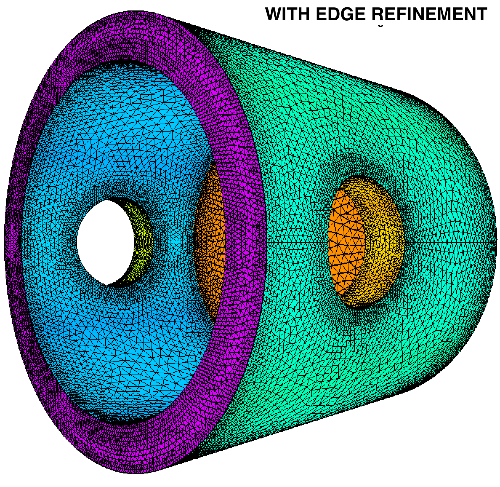
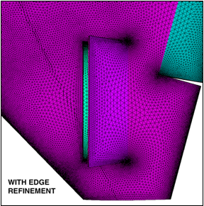
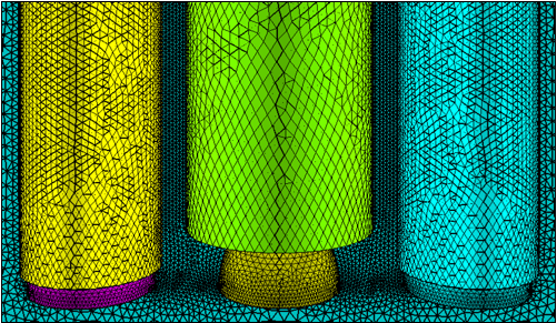
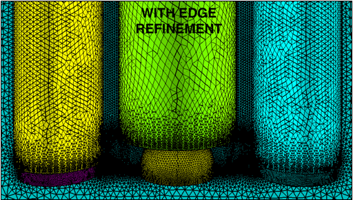
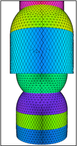
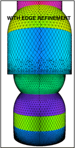
Piston
(CAD geometry definition).
A simple piston. Reference length is set equal to the minimum bounding box size
of the piston. Without and with edge refinement.
aflr4 -i piston.egads -o piston_new.surf -log
aflr4 -i piston.egads -o
piston_new2.surf -log -er_all
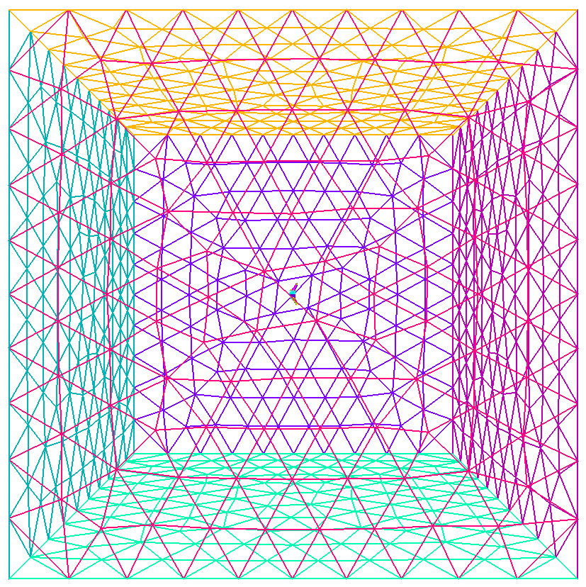
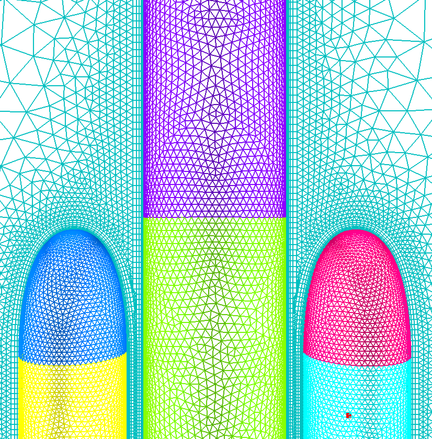
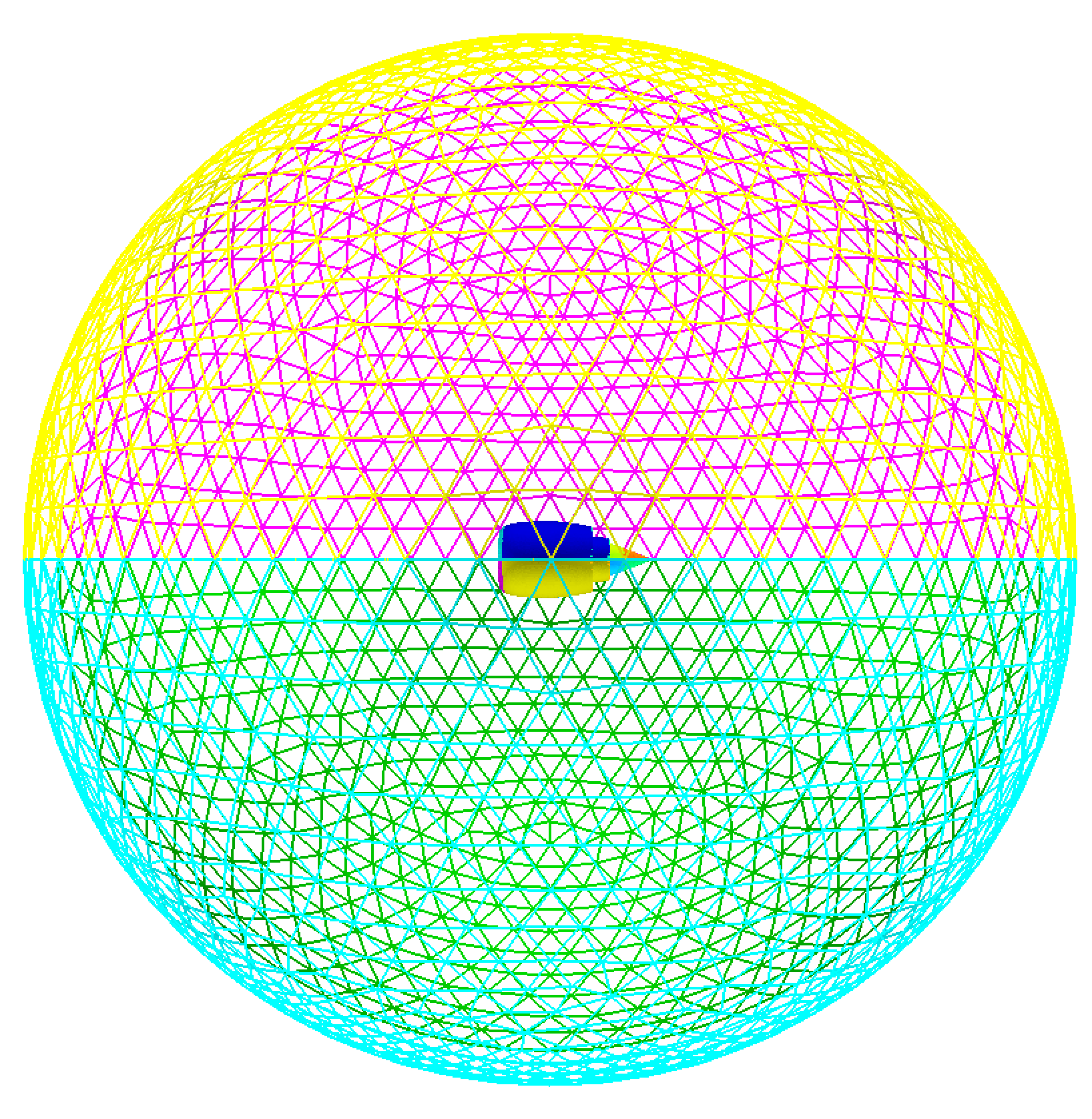
Nose
(CAD geometry definition).
A simple nose cone in a farfield. Reference length is set equal to the minimum
bounding box size of the nose cone only. Farfield IDs are are
specified.
aflr4 -i
nose.egads -o nose_new.surf -log -ff_ids 1-6
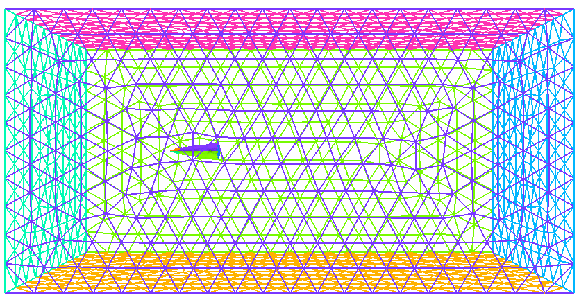
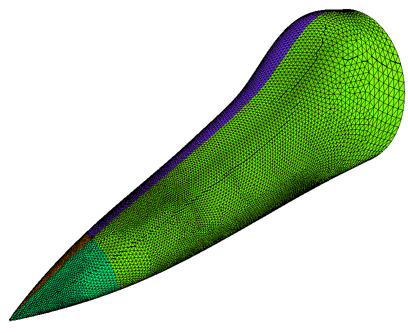
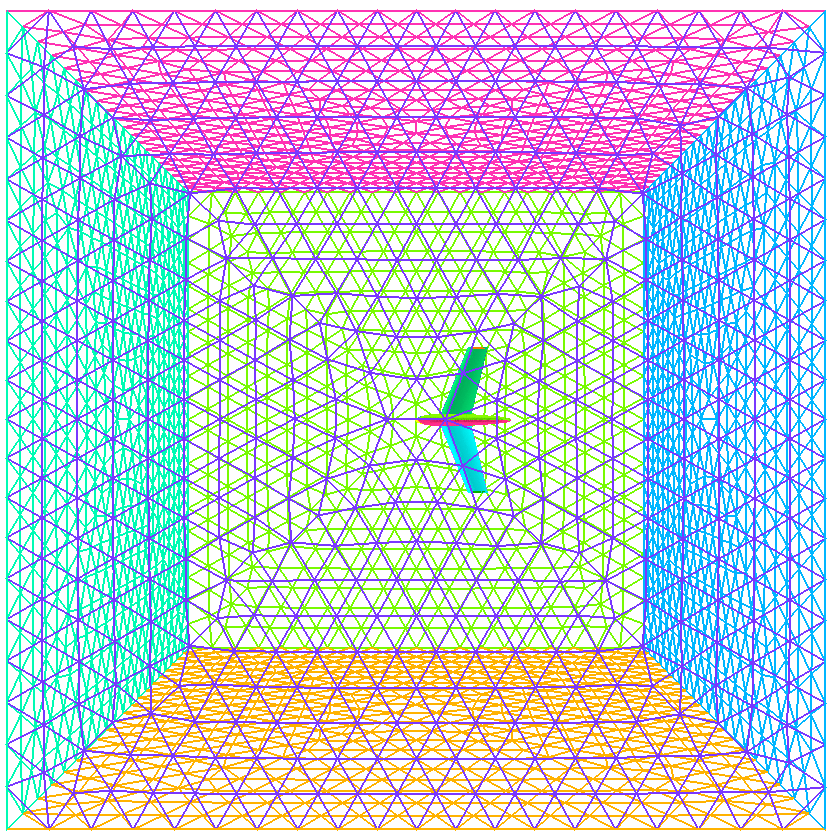
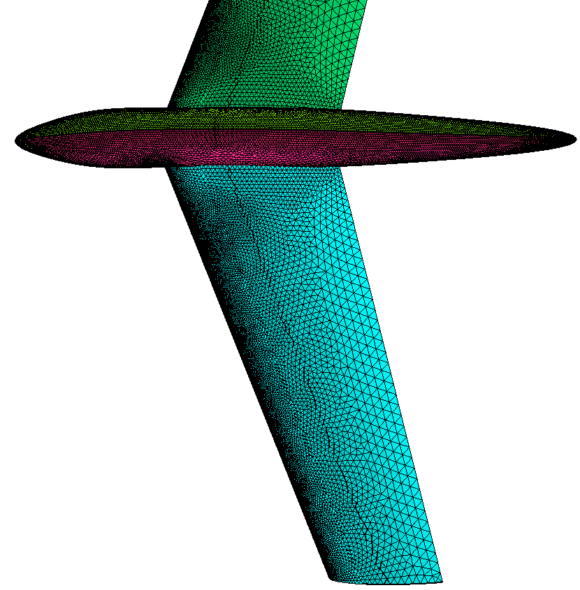
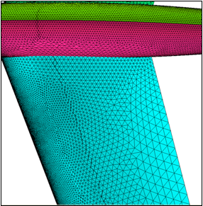
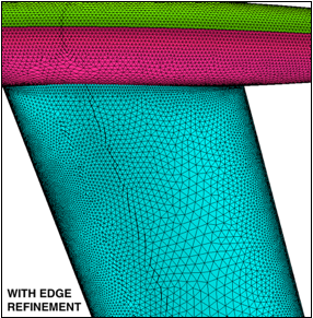
Glider (CAD geometry
definition).
A simple glider in a farfield. Reference length is set equal to 3, which is
about the same as the wing cord length at the wing tip. Without and with edge
refinement.
aflr4 -i glider -o glider_new.surf -ff_ids 1-6 -ref_len 3 -log
aflr4 -i glider -o glider_new2.surf -ff_ids 1-6 -ref_len 3 -log -er_all
A compatible volume mesh
can be generated using AFLR3.
aflr3 -i glider_new -blc -blds 0.0001 -log
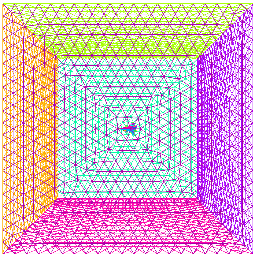
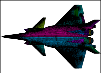
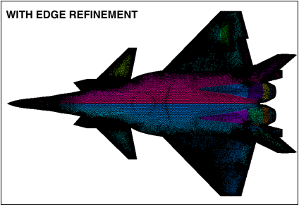
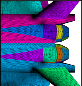
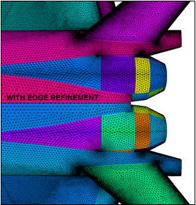
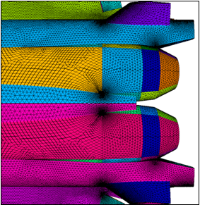
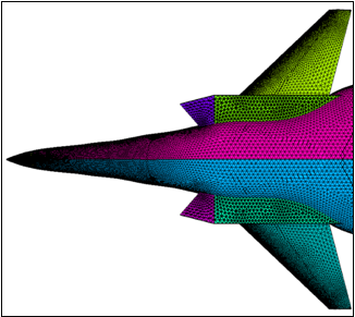
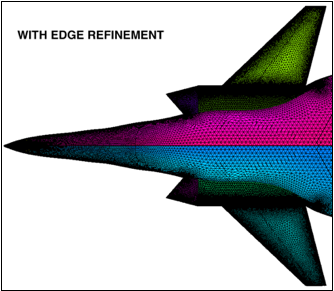
Aircraft (CAD geometry
definition).
A
generic fighter configuration with an added farfield. Reference length is set
equal to 1, which is about the same as the wing cord length at the wing tip. Without
and with edge refinement.
aflr4 -i aircraft -o aircraft_new.surf -ref_len 1 -add_ff -log
aflr4 -i aircraft -o aircraft_new2.surf -ref_len 1 -add_ff -log -er_all
A compatible volume mesh can be generated using AFLR3.
aflr3 -i aircraft_new -blc -blds 0.0001 -log
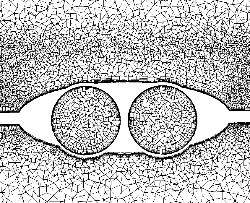
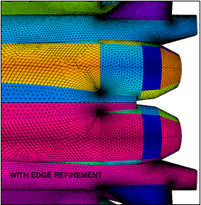
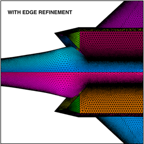
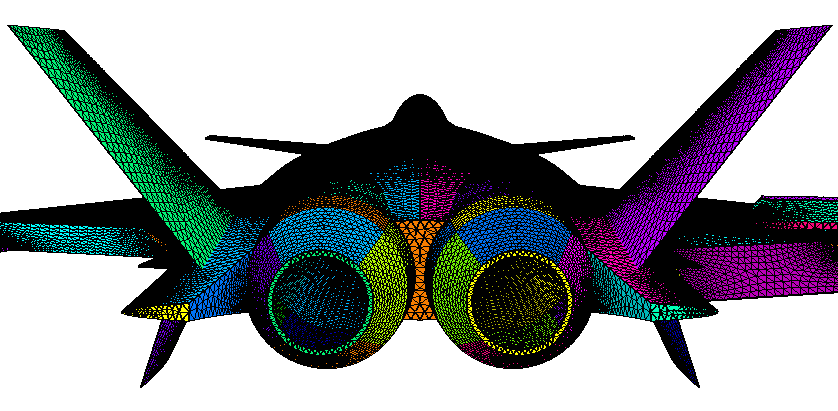
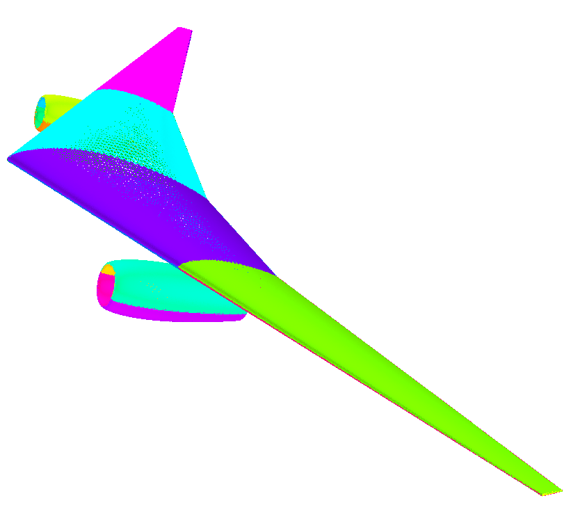
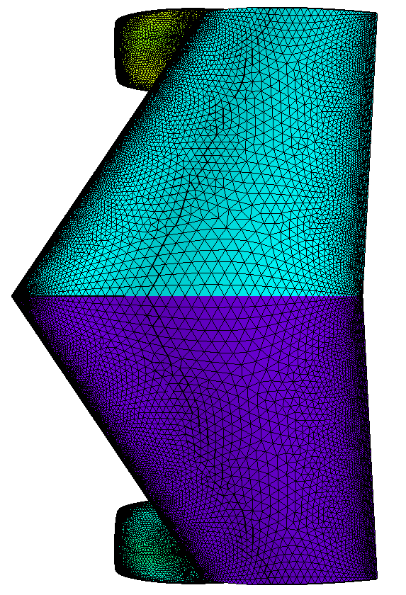
Wing and Nacelle (CAD
geometry definition).
A
generic wing and nacelle configuration. Reference length is set equal to 20,
which is about the same as the wing cord length at mid-span. Edge
refinement is added for resolution at the trailing edge and witng
tip. Proximity checking automatically detects and reduces the spacing between
the wing and each nacelle. Note that the farfield spacing has been increased to
reduce the number of volume elements that will be generated by AFLR3 in the
outer region.
aflr4 -i wingpod
-o wingpod_new.surf -log -ff_ids 19-24 -er_all -ref_len 40 -Re_l 60e6
A compatible volume mesh
can be generated using AFLR3.
aflr3 -i wingpod_new -blc -y+ 1 -refx 40 -Re_l 60e6 -blrm 1.3 -log
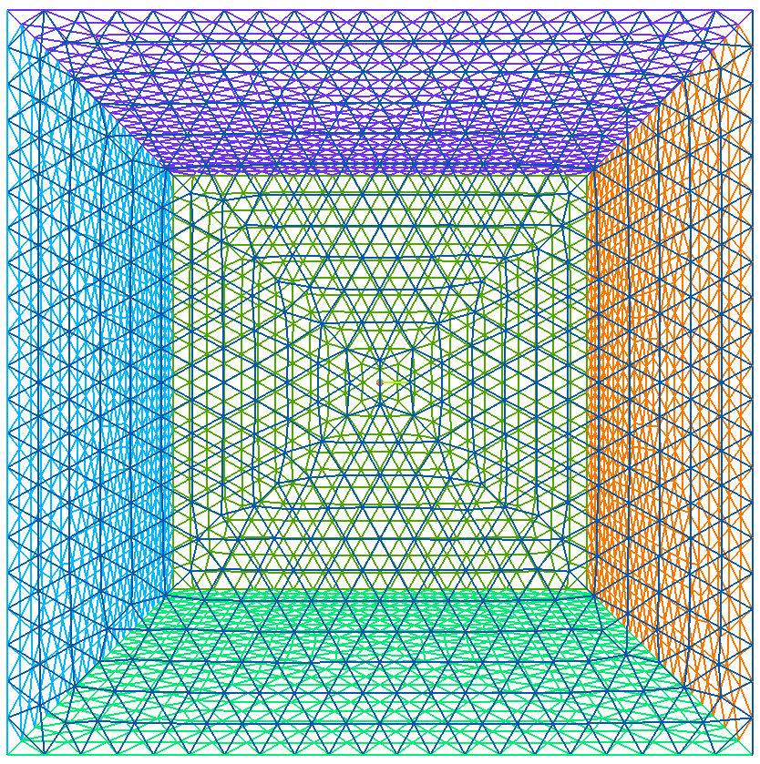
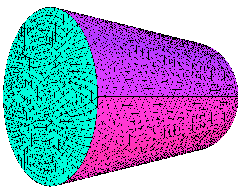
Simple can with discrete geometry definition.
A simple can. Reference length is set equal to the minimum bounding box size of
the can.
aflr4 -i can.surf -o can_new.surf
-log
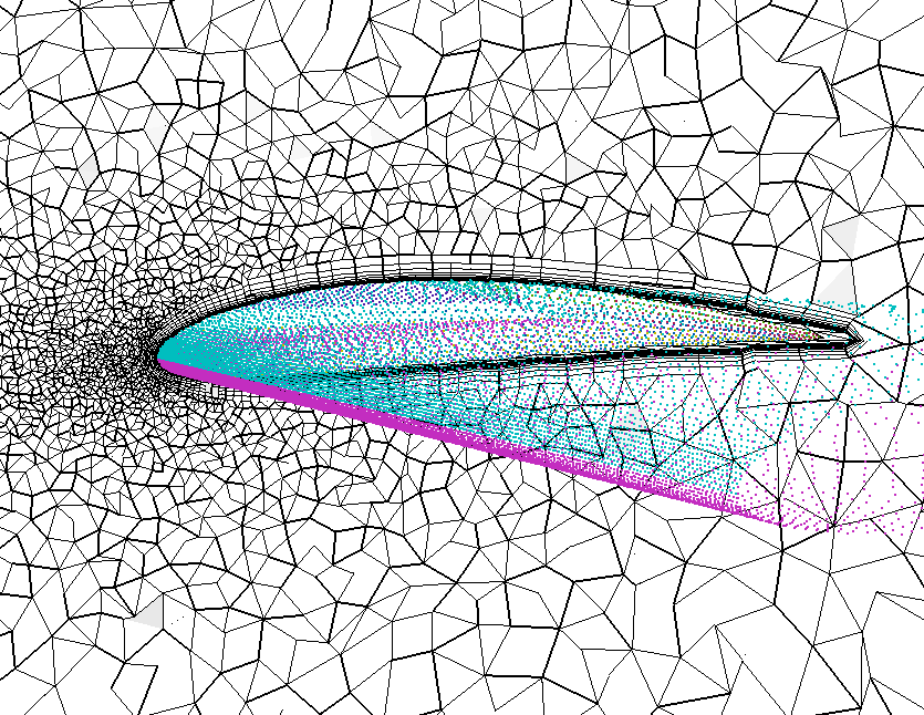
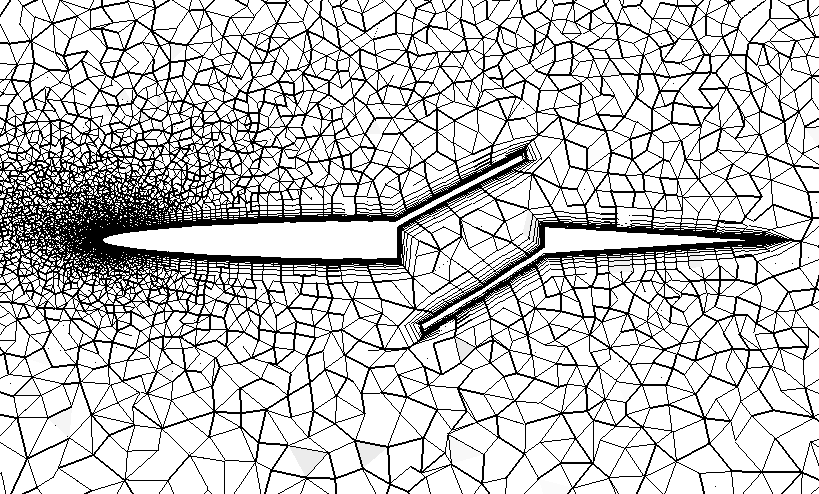
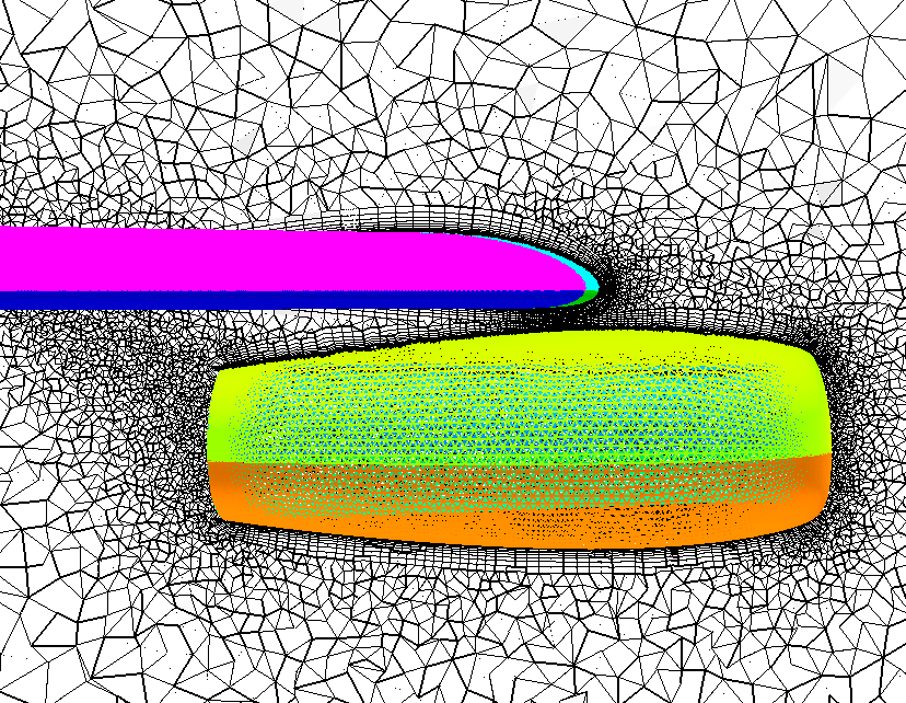
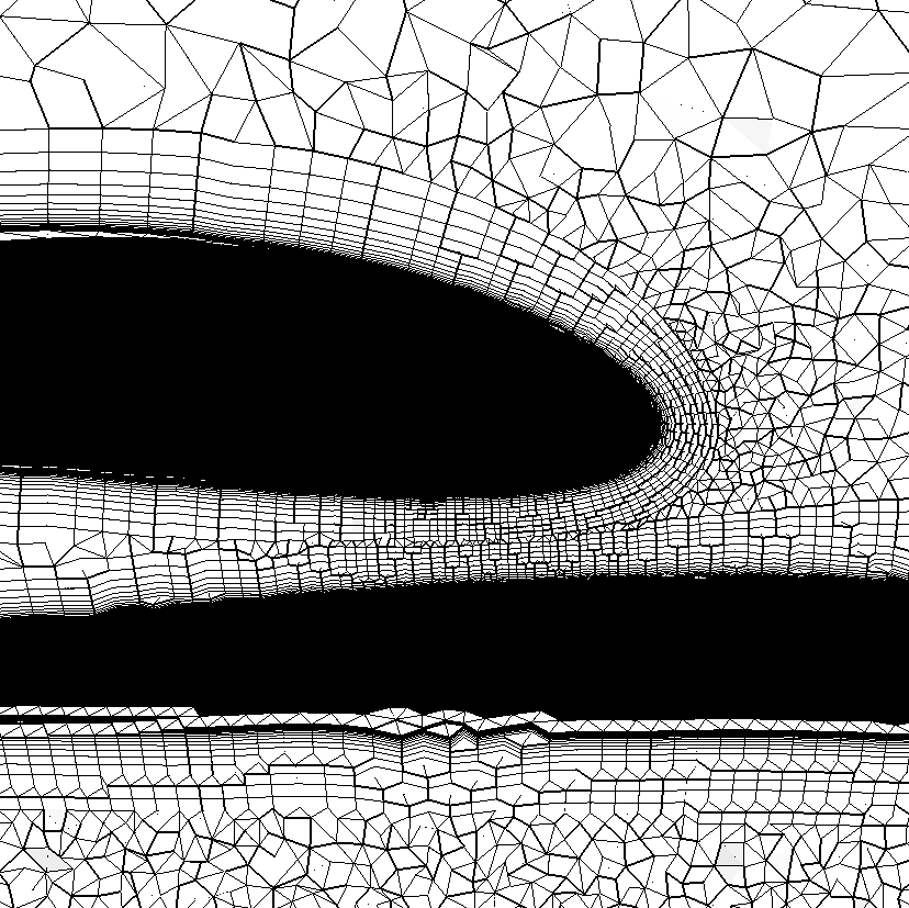
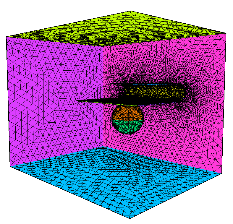
Wing & Wake Sheet with
discrete geometry definition.
A
simple wing and transparent wake sheet with non-manifold connection with edge
refinement. Reference length is set equal to the wing chord length.
aflr4 -i wing_wake
-o wing_wake_new.surf -ff_ids 1-4 -trnsp_bl_ids 5, ref_len=2 -er_all -log
A compatible volume mesh can be generated using AFLR3.
aflr3 -i wing_wake_new -blc -blds 0.0001 -log
Multi-body
generic cases 1 through 8 with discrete geometry definition.
A set of simple multi-body generic cases. Reference length is set equal to the
minimum bounding box size of the domain in each case. Proximity checking and
spacing modification is automatically used in the regions where the components
are in close proximity.
aflr4 -i case1.surf -o case1_new.surf -log -ff_ids 2,6
aflr4 -i
case2.surf -o case2_new.surf -log -ff_ids
2,6
aflr4 -i
case3.surf -o case3_new.surf -log -ff_ids
3,6
aflr4 -i case4.surf -o case4_new.surf -log -ff_ids 24,27
aflr4 -i case5.surf -o case5_new.surf -log -ff_ids 2, -int_ids 1,3,5,6
aflr4 -i
case6.surf -o case6_new.surf -log -ff_ids
1,2
aflr4 -i case7.surf -o case7_new.surf -log -ff_ids 16,17
aflr4 -i
case8..surf -o case8._new.surf -log -ff_ids 16,17
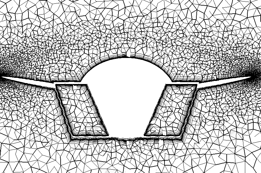
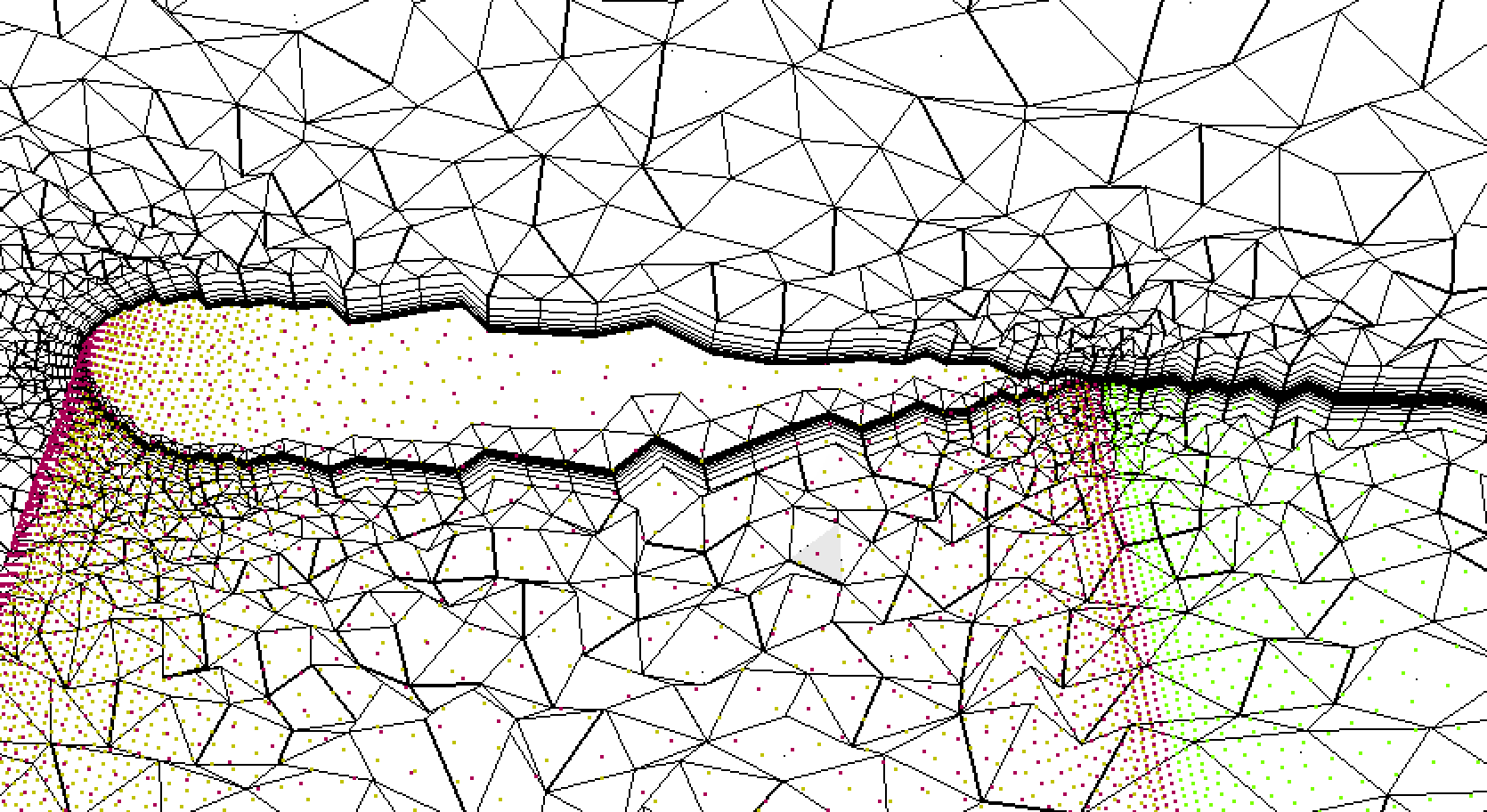
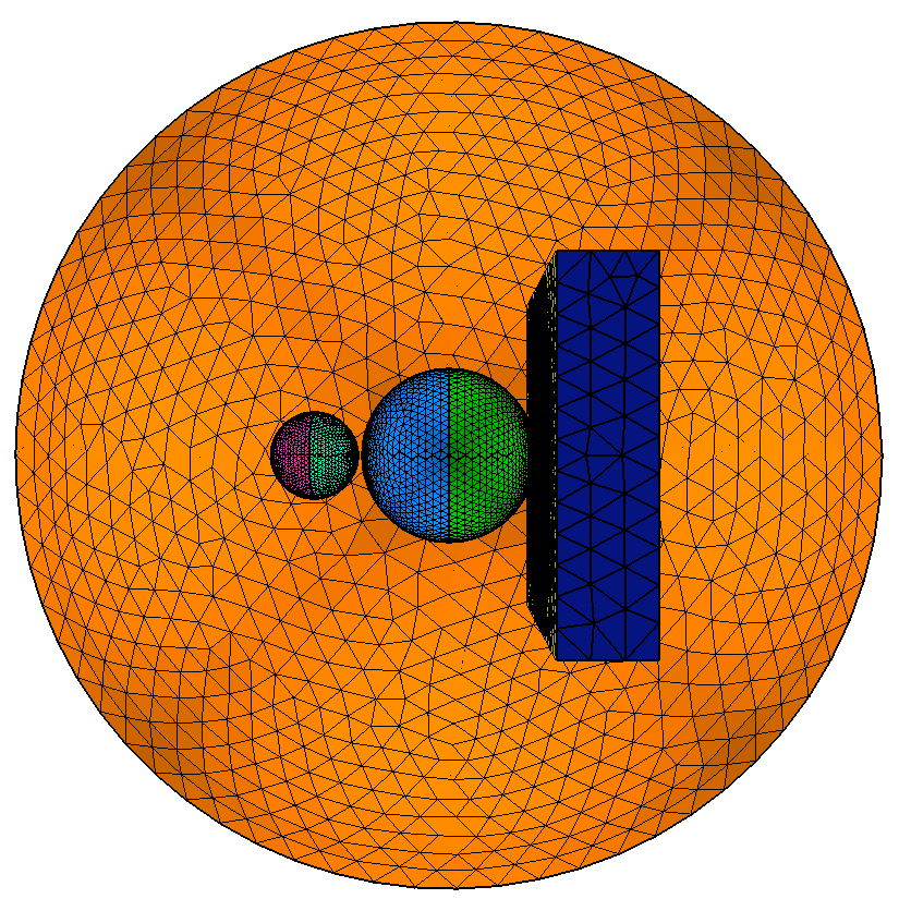
Multi-body
generic case 9 with discrete geometry definition.
A simple multi-body generic case with a symmetry plane. Reference length is set
equal to the minimum bounding box size of the inner components. Farfield
and symmetry plane IDs are are specified. BL
thickness with minimal isotropic region thickness is also specified. Proximity
checking and spacing modification is automatically used in the regions where
the components are in close proximity.
aflr4 -i case9..surf
-o case9._new.surf -log -ff_ids 2-5 -int_ids 1, -BL_thickness 0.1 -min_ncell 1
A compatible volume mesh can be generated using AFLR3. For
this case the proximity checking and spacing
modification process provide spacing sufficient to support BL generation
between nearby components.
aflr3 -i case9_new -blc -blrm 1.3 -blds 0.0001 -log
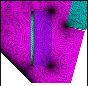
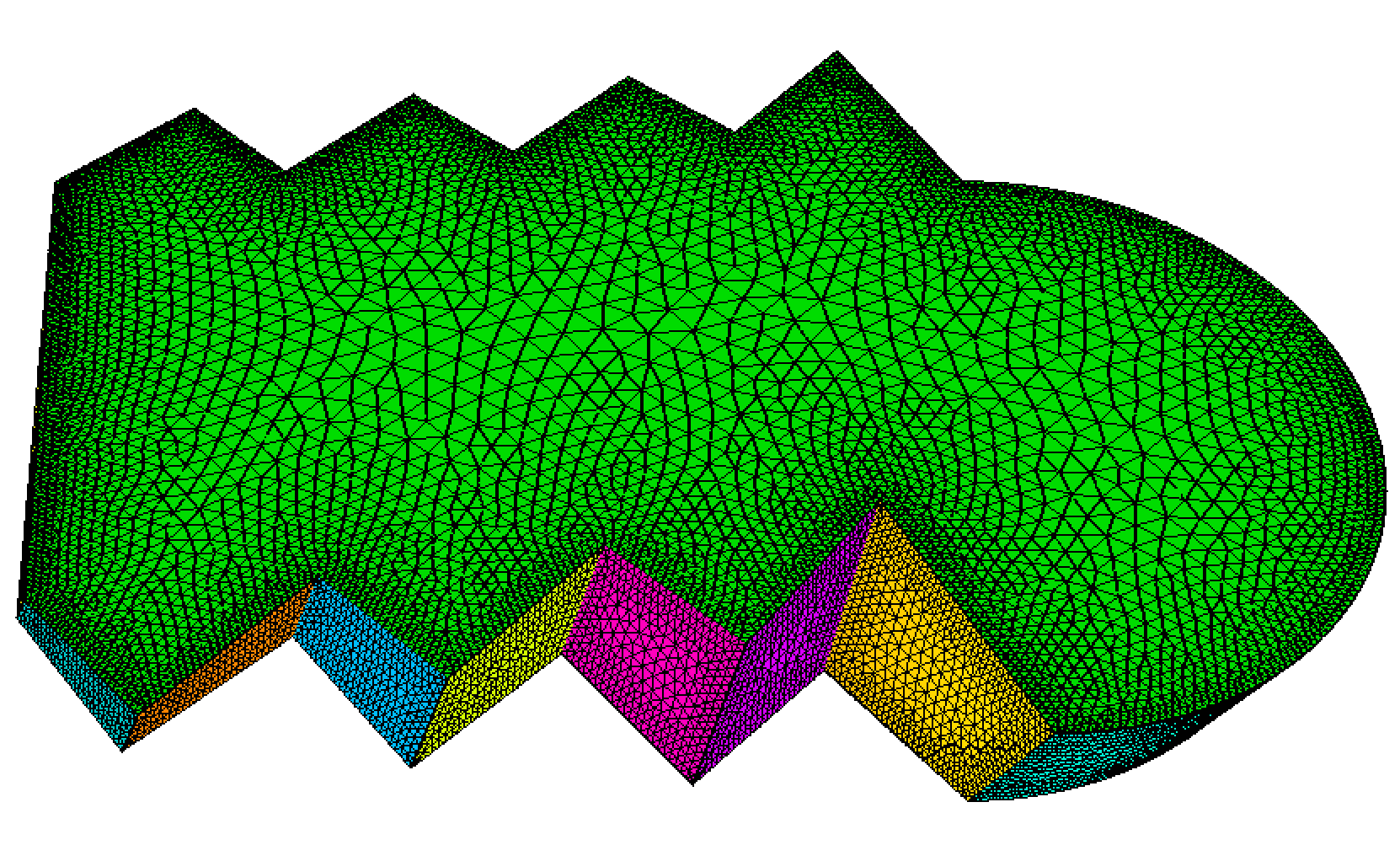
Cover
plate with discrete geometry definition.
A cover plate. Reference length is set equal to 100 (close to the mean bounding
box size of the domain).
aflr4 -i
cover_plate.surf -o cover_plate_new.surf -log -ref_len
100
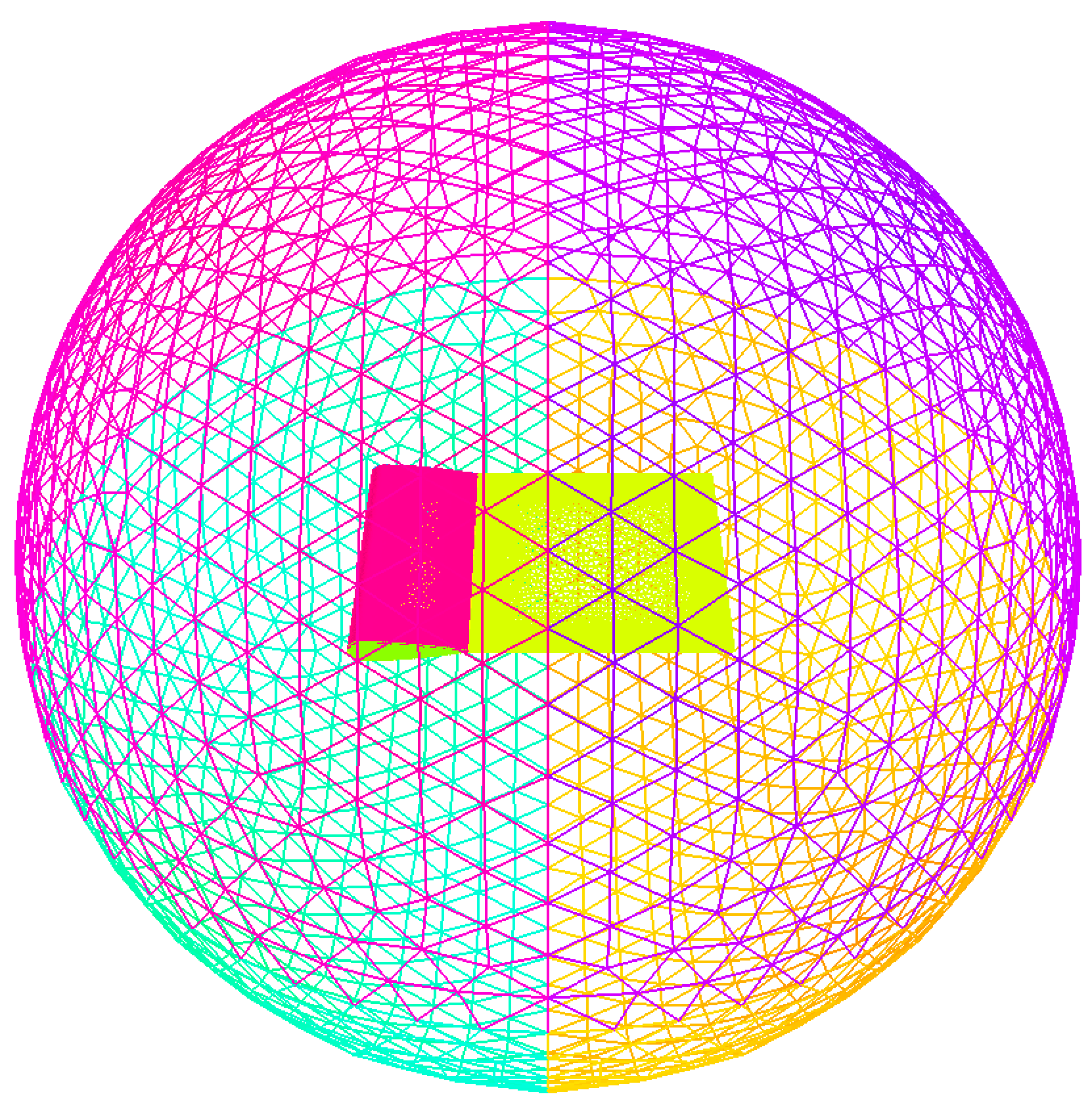
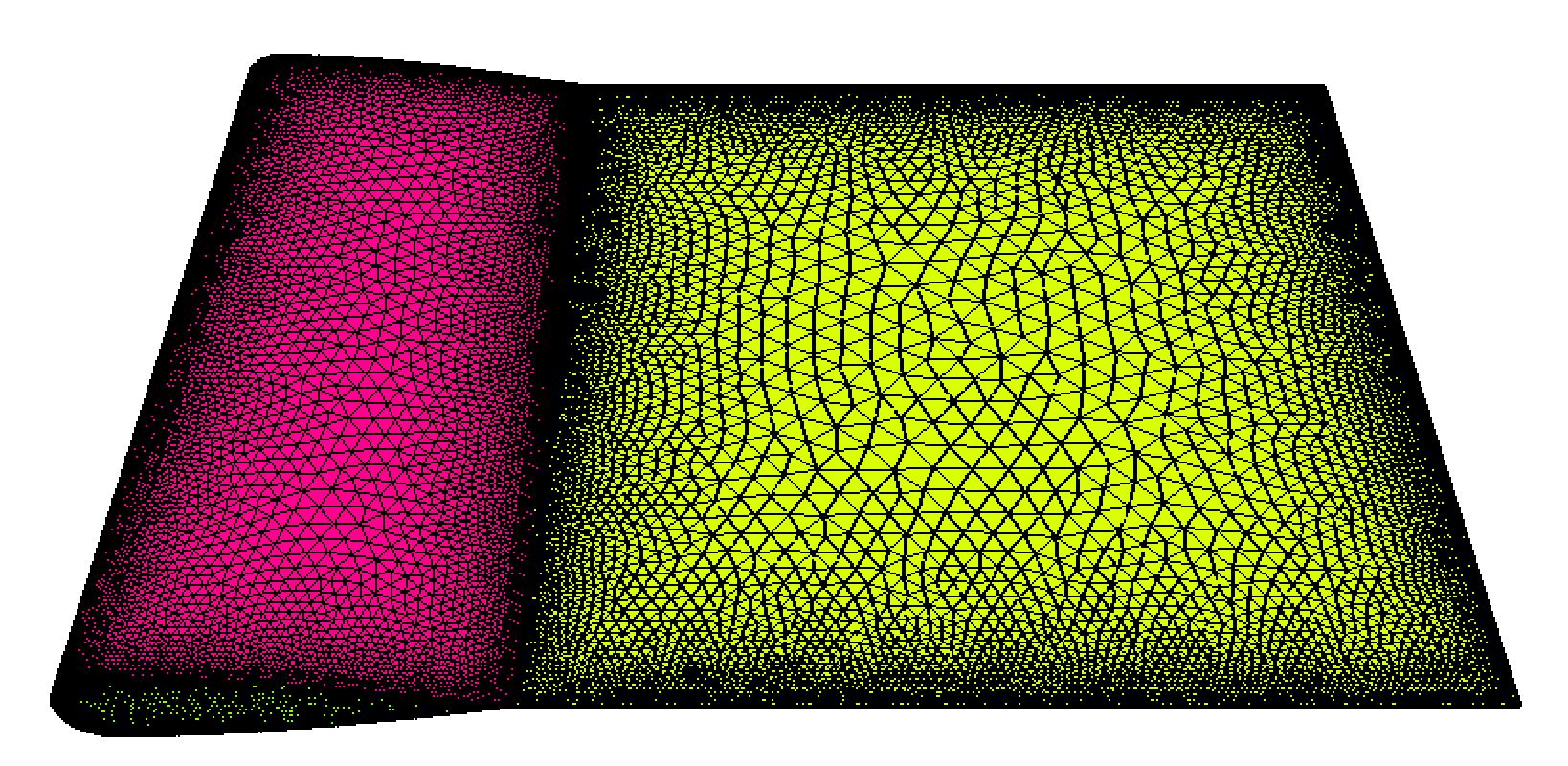
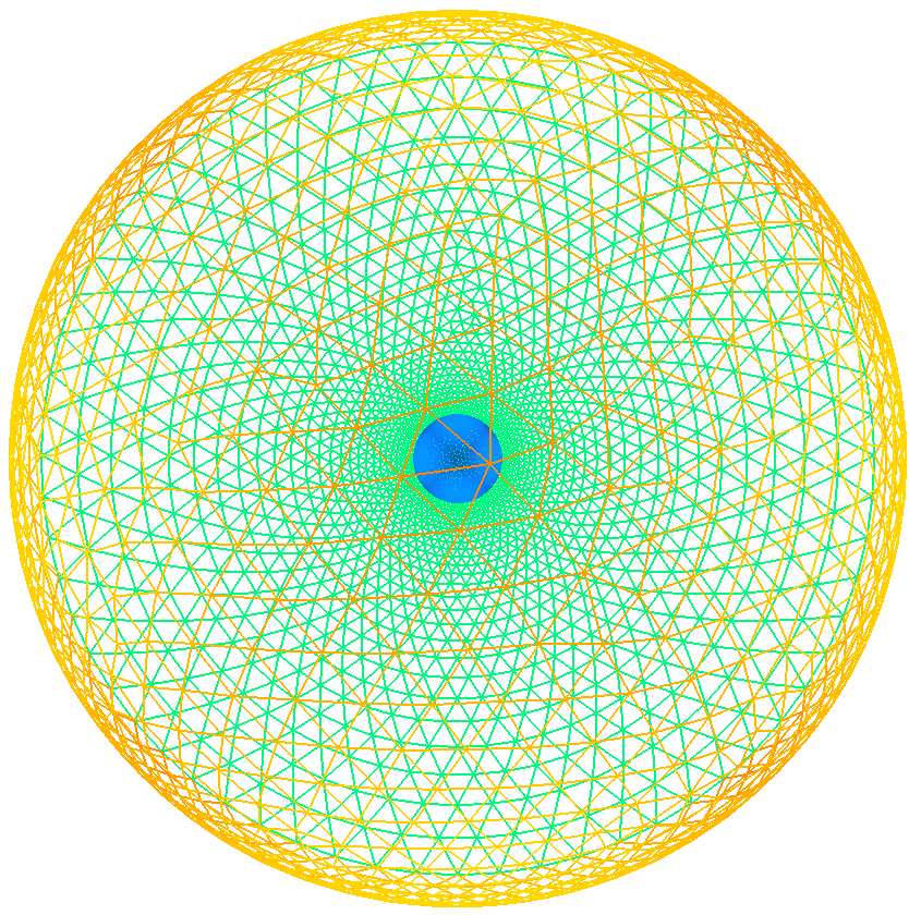
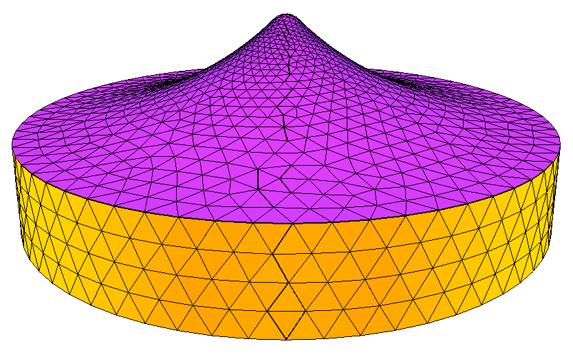
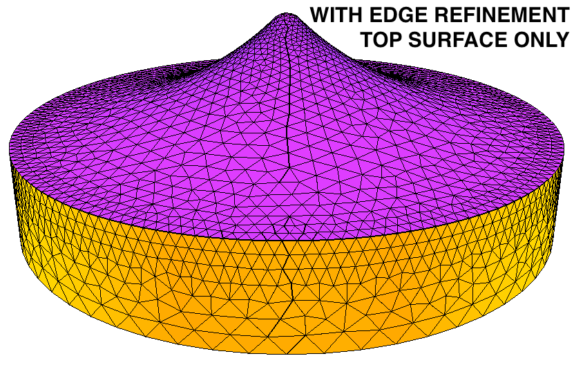
Bump
disk with discrete geometry definition.
A bump disk. Reference length is set equal to the minimum bounding box size of
the domain. Without and with edge refinement on top surface only.
aflr4 -i bump -o bump_new.surf -log
aflr4 -i bump -o bump_new2.surf -log -erw_ids 3, -erw_list 1,
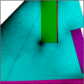
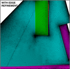
Edge
test with discrete geometry definition.
A simple configuration for testing edge refinement.
aflr4 -I edge_test -o edge_test_new.surf -log -er_all
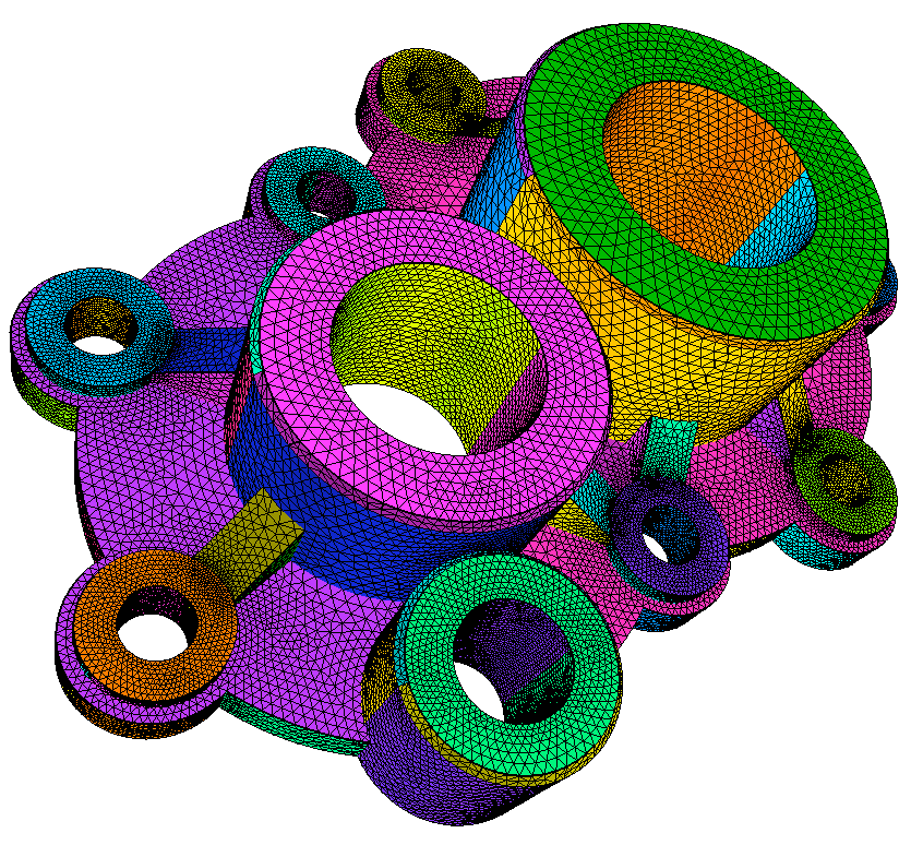
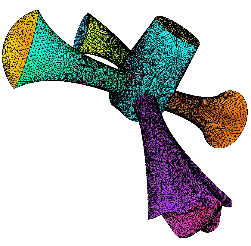
Horn
with discrete geometry definition.
A generic horn manifold. Reference length is set equal to the minimum bounding
box size of the domain.
aflr4 -i horn.surf -o horn_new.surf
-log
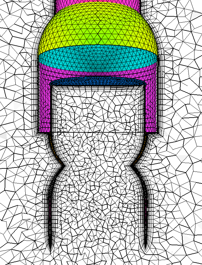
Plug with discrete
geometry definition.
A simple mechanical plug. Reference length is set equal to the minimum bounding
box size of the domain.
aflr4 -I plug.surf
-o plug_new.surf -log
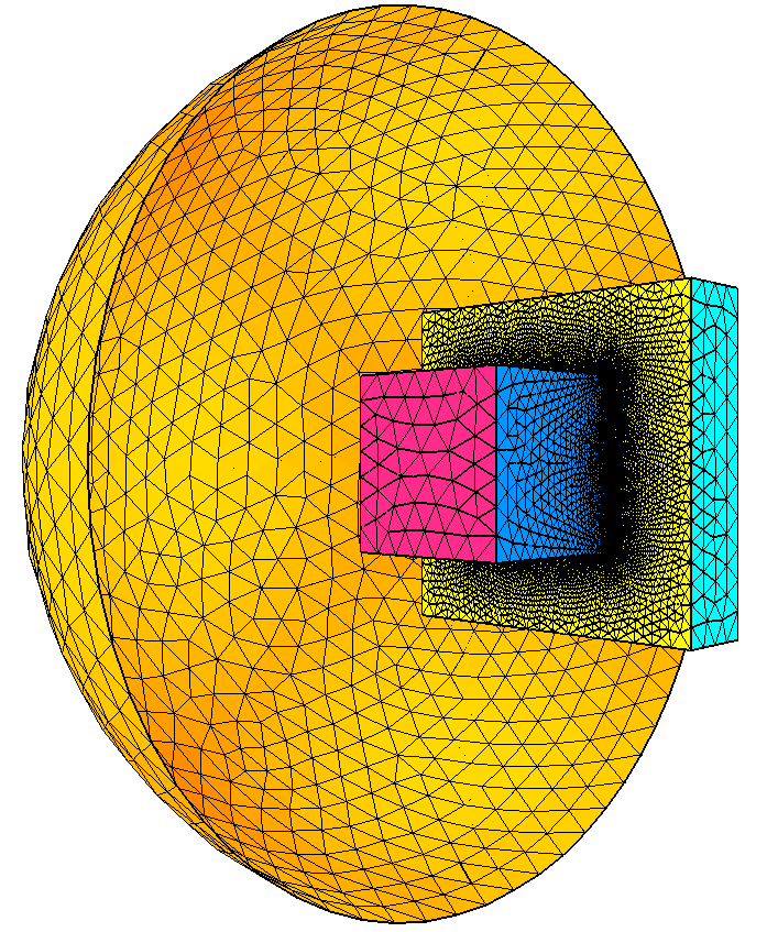
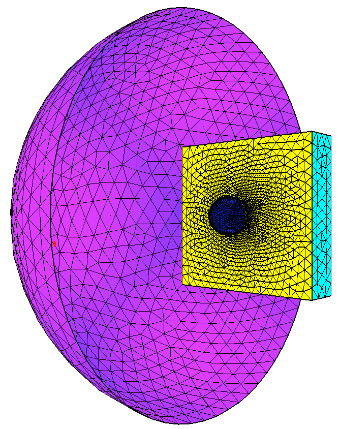
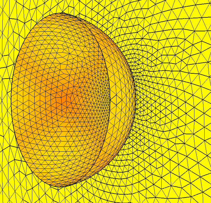
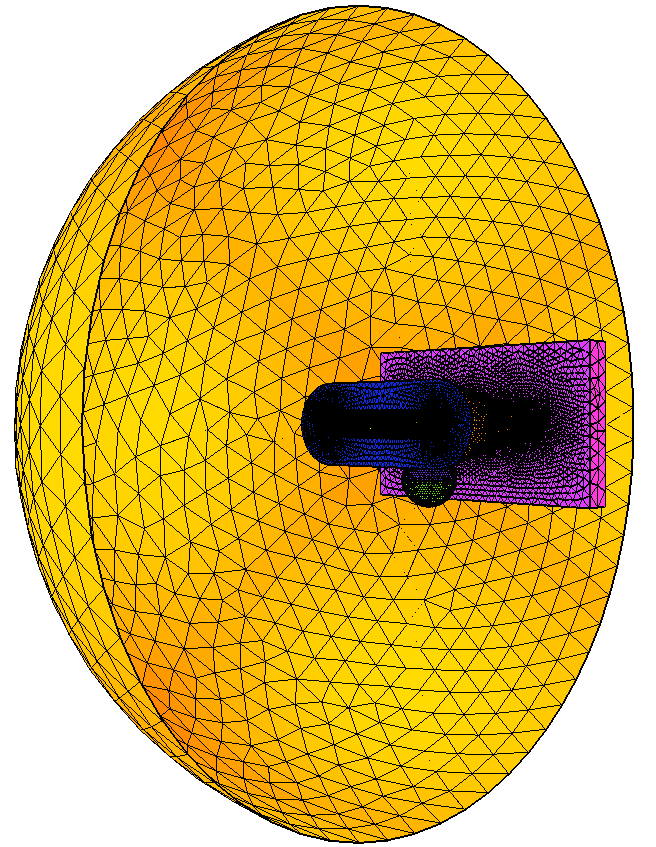
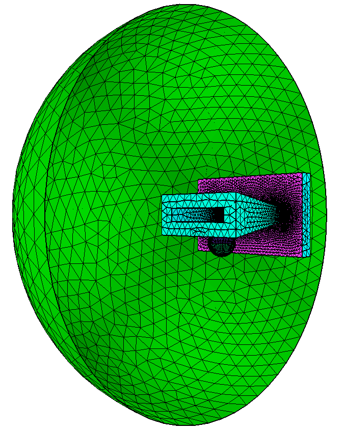
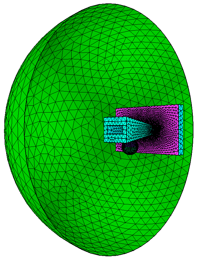
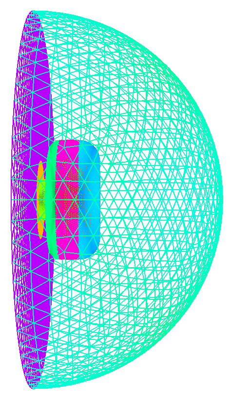
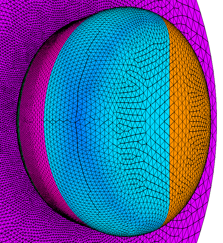
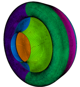
Knob with discrete
geometry definition.
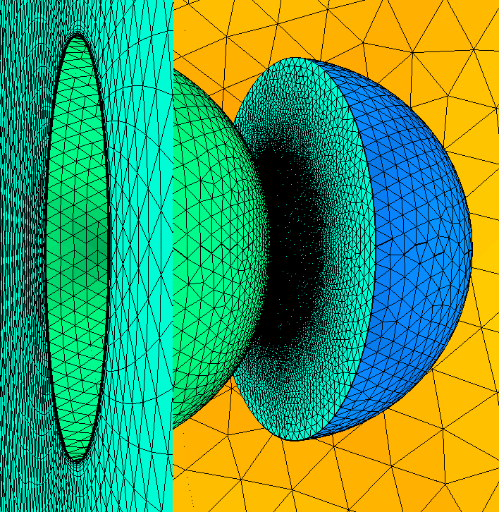
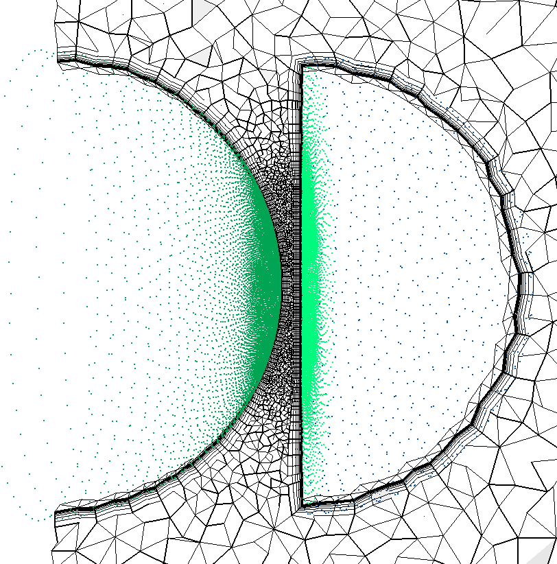
A simple knob with a farfield and symmetry plane. Reference length is set equal
to the diameter of the knob. Farfield and symmetry plane IDs are are specified. BL thickness with minimal isotropic region
thickness is also specified. In this case part of the knob is very close to the
symmetry plane. To allow for proximity checking the symmetry plane was split
into two pieces; an inner one which is treated as a symmetry plane and an outer
surface that is treated like a solid surface. This allows proximity checking to
identify the outer surface as another component and provide reduced spacing in
the narrow region between the outer symmetry plane like surface and the knob.
Note that in the future symmetry planes will support proximity checking and the
split surface treatment will not be required.
aflr4 -i knob -o knob_new.surf -log -ff_ids 1, -int_ids 2, -ref_len 4 -BL_thickness 0.15 -min_ncell 1
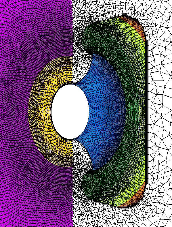
A compatible volume mesh
can be generated using AFLR3. For this case the proximity checking and spacing modification process provides spacing
sufficient to support BL generation between the knob and surface adjacent to
the symmetry plane.
aflr3 -i
knob_new -blc -blds 0.0001 -log -bls 4-11
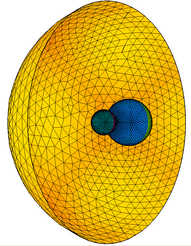
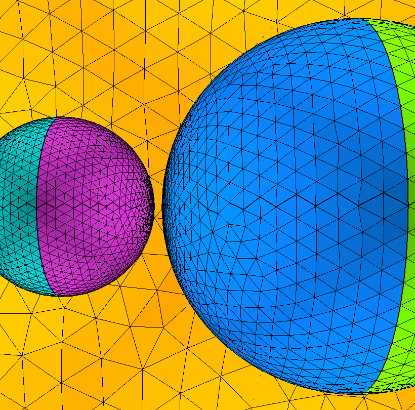
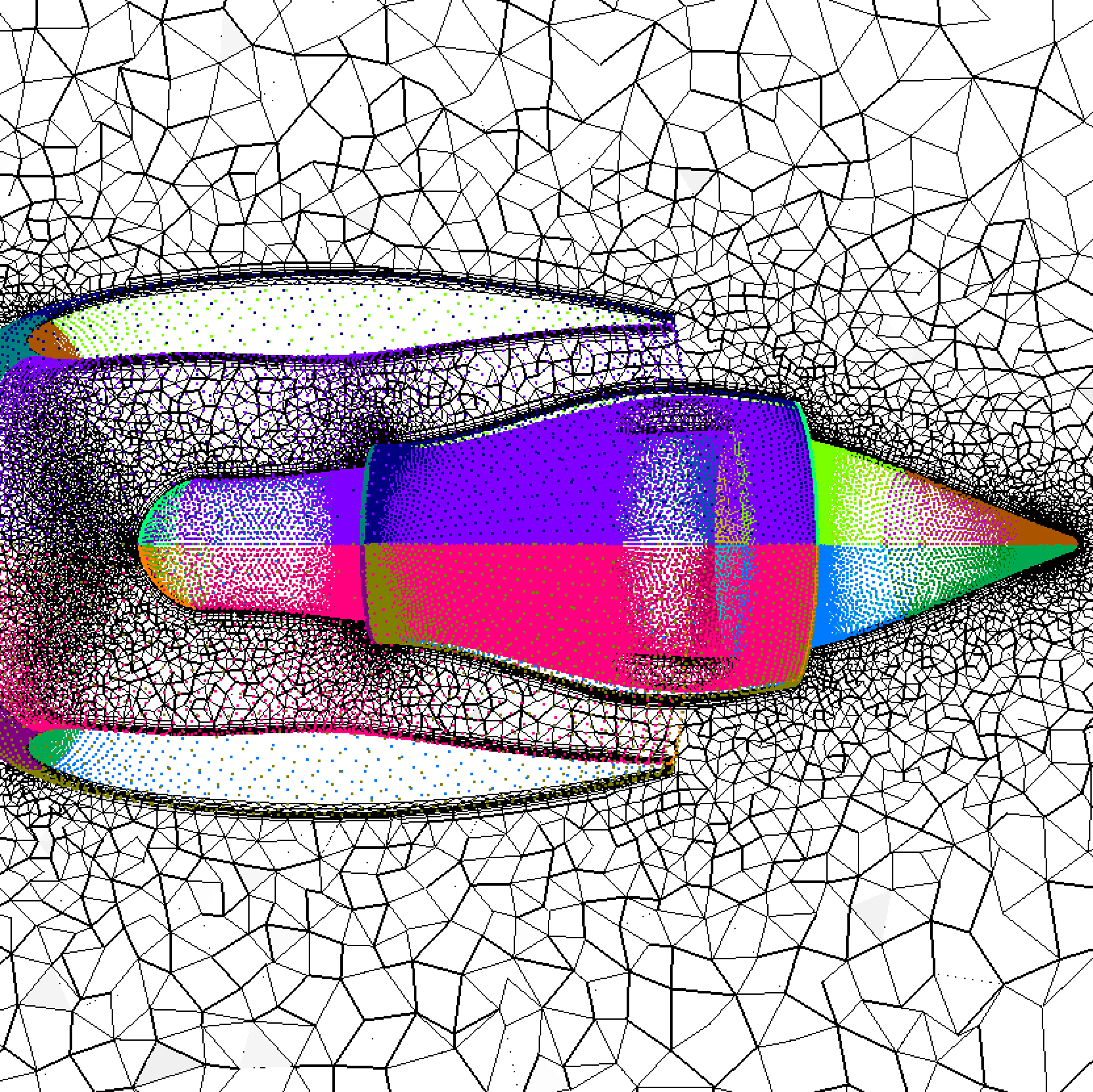
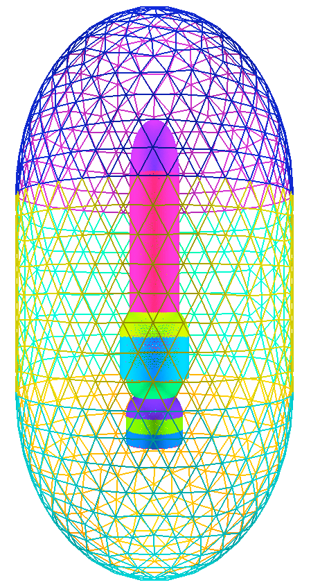
Launch vehicle with discrete geometry definition.
A launch vehicle with two strap-on boosters in a farfield. Reference length is
set equal to the main booster payload diameter. Farfield IDs are are specified. BL
thickness with minimal isotropic region thickness is also specified. Proximity
checking and spacing modification is automatically used in the regions where
the components are in close proximity.
aflr4 -i lv2b -o lv2b_new.surf -log -ff_ids 16-21 -int_ids 45,46,47,68,69,70 -ref_len
40 -Re_l 125e6
A compatible volume mesh can be generated using AFLR3. For
this case the proximity checking and spacing
modification process provides spacing sufficient to support BL generation between
nearby components.
aflr3 -i lv2b_new -blc -y+ 1 -refx 40 -Re 125e6 -log
A launch vehicle with two strap-on boosters with a symmetry plane in a farfield
is also provided. Other than the geometry all other parameters are the same.
Without and with edge refinement.
aflr4 -i
lv2b_sym -o lv2b_sym_new.surf -log -log -ff_ids 16-21
-int_ids 45,46,47,68,69,70 -ref_len
40 -Re_l 125e6
aflr4 -i lv2b_sym -o lv2b_sym_new2.surf -log -ff_ids 16-21 -int_ids
45,46,47,68,69,70 -ref_len 40 -Re_l
125e6 -er_all
A compatible volume mesh
can be generated using AFLR3. For this case the proximity checking and spacing modification process provides spacing
sufficient to support BL generation between nearby components.
aflr3 -i lv2b_sym_new -blc -y+ 1 -refx 40 -Re 125e6 -log
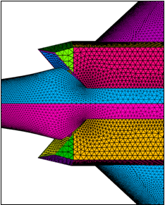
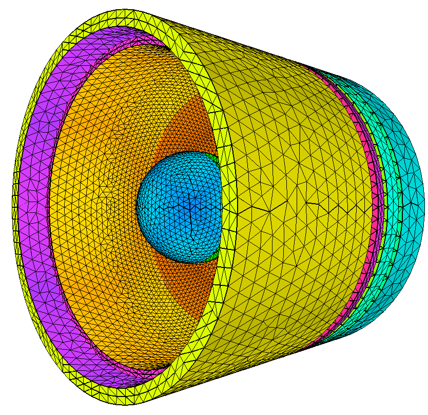
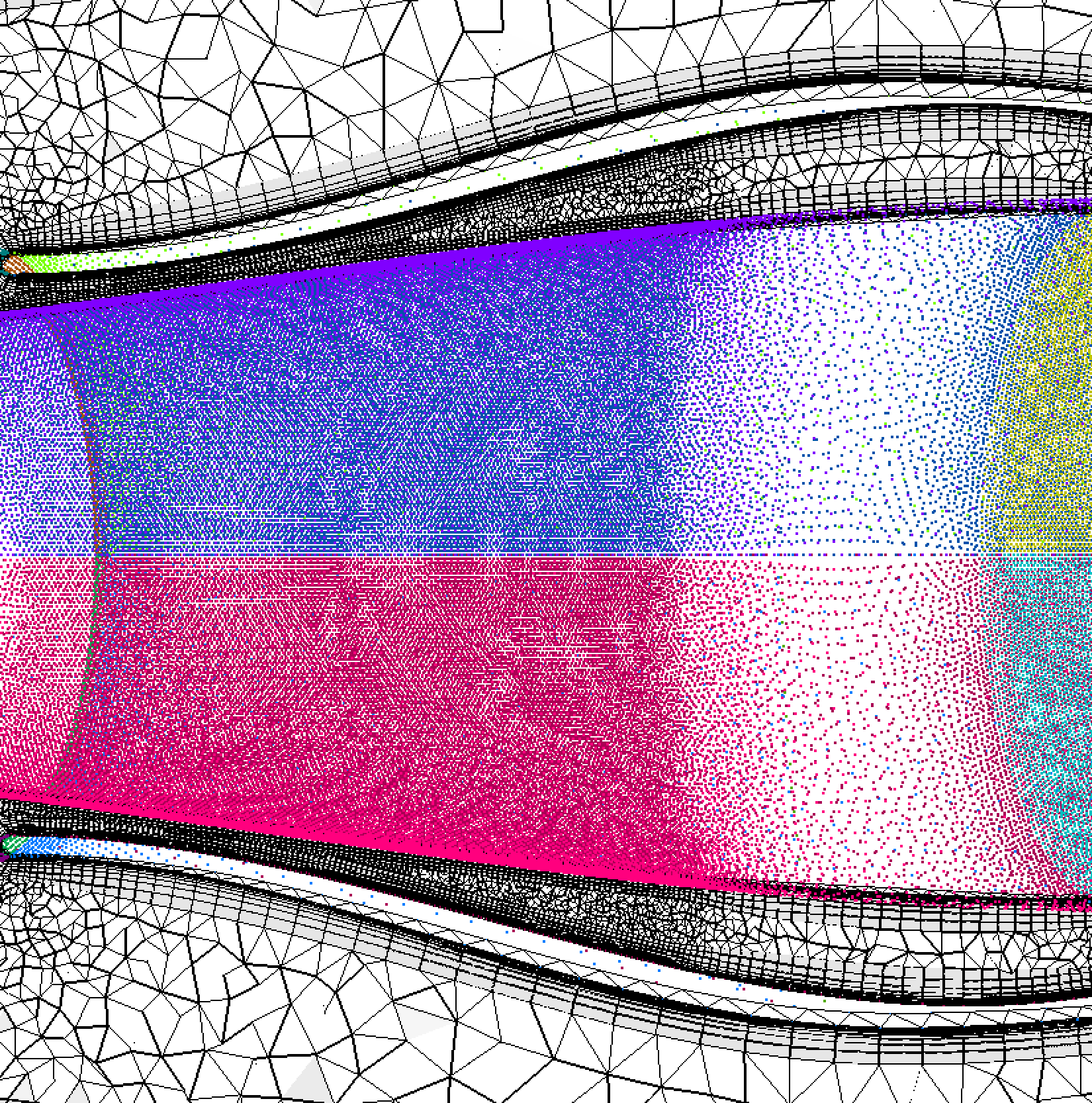
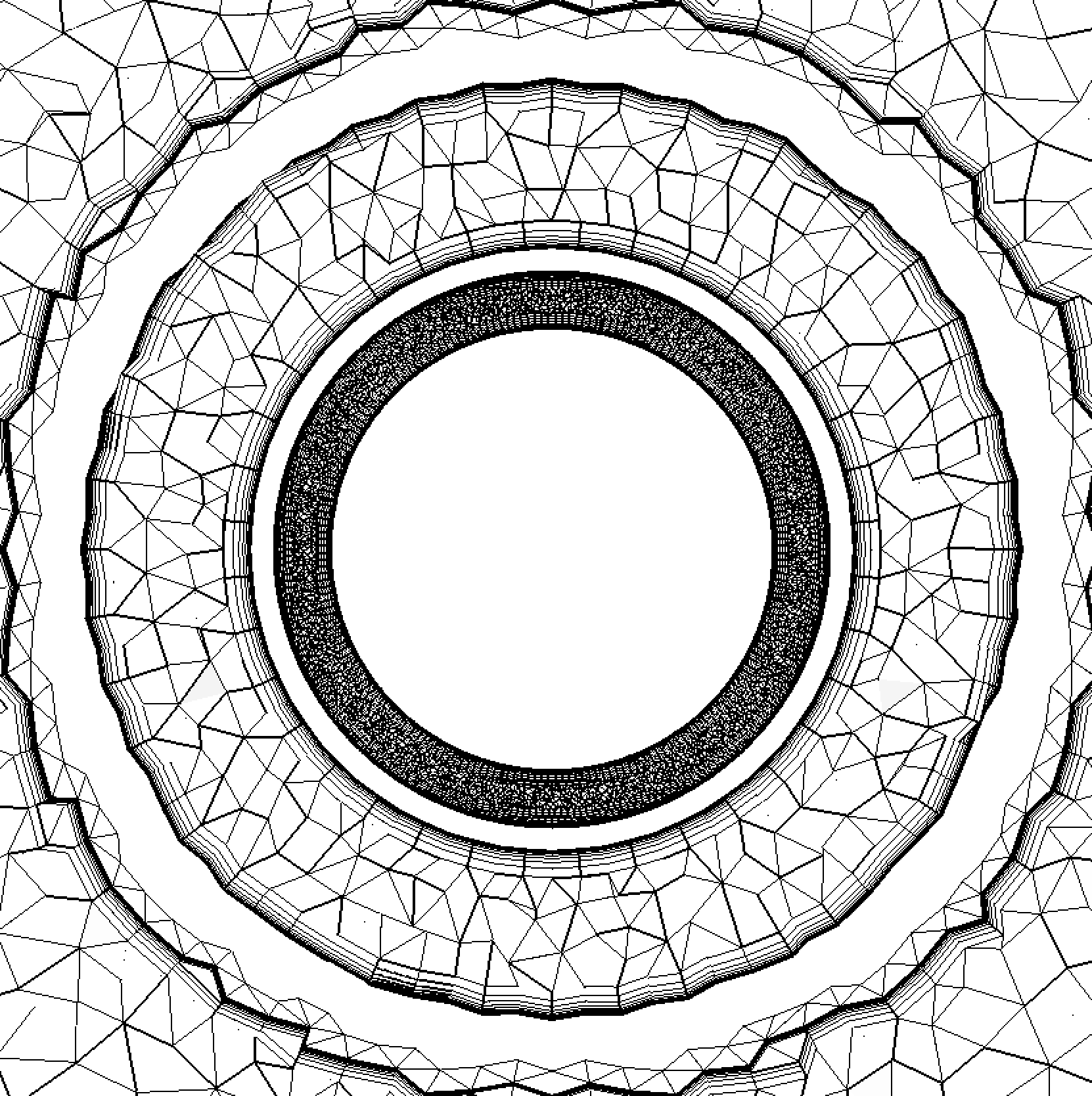
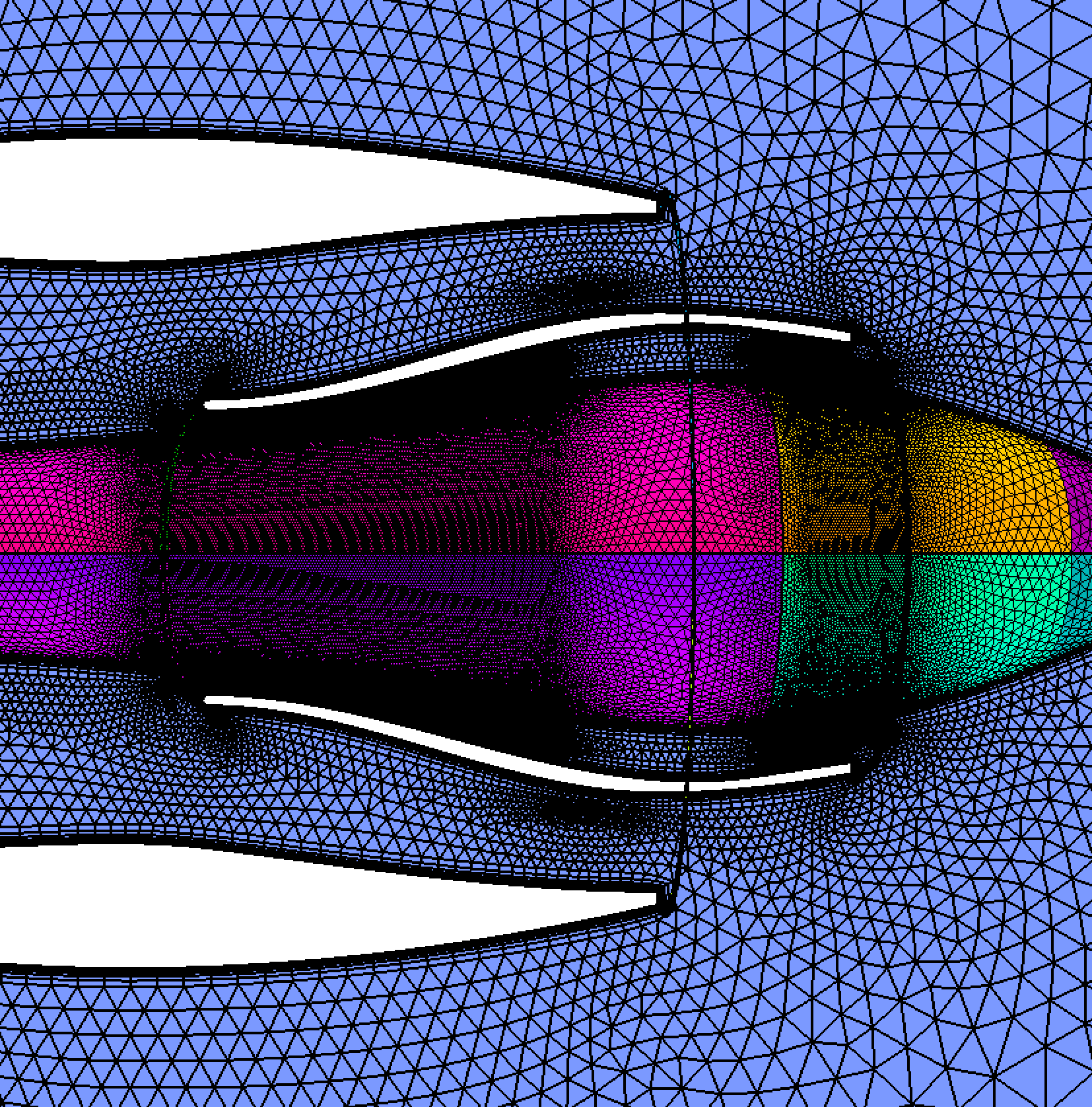
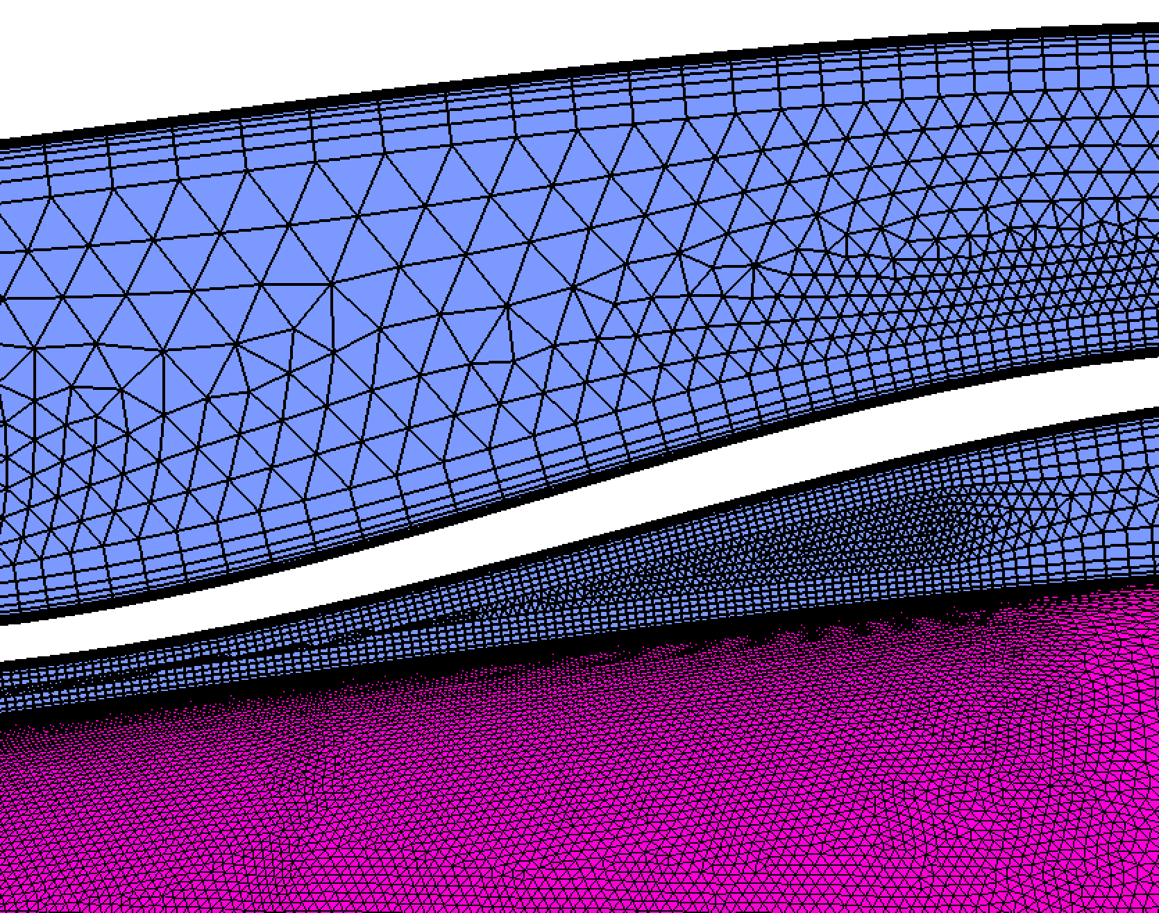
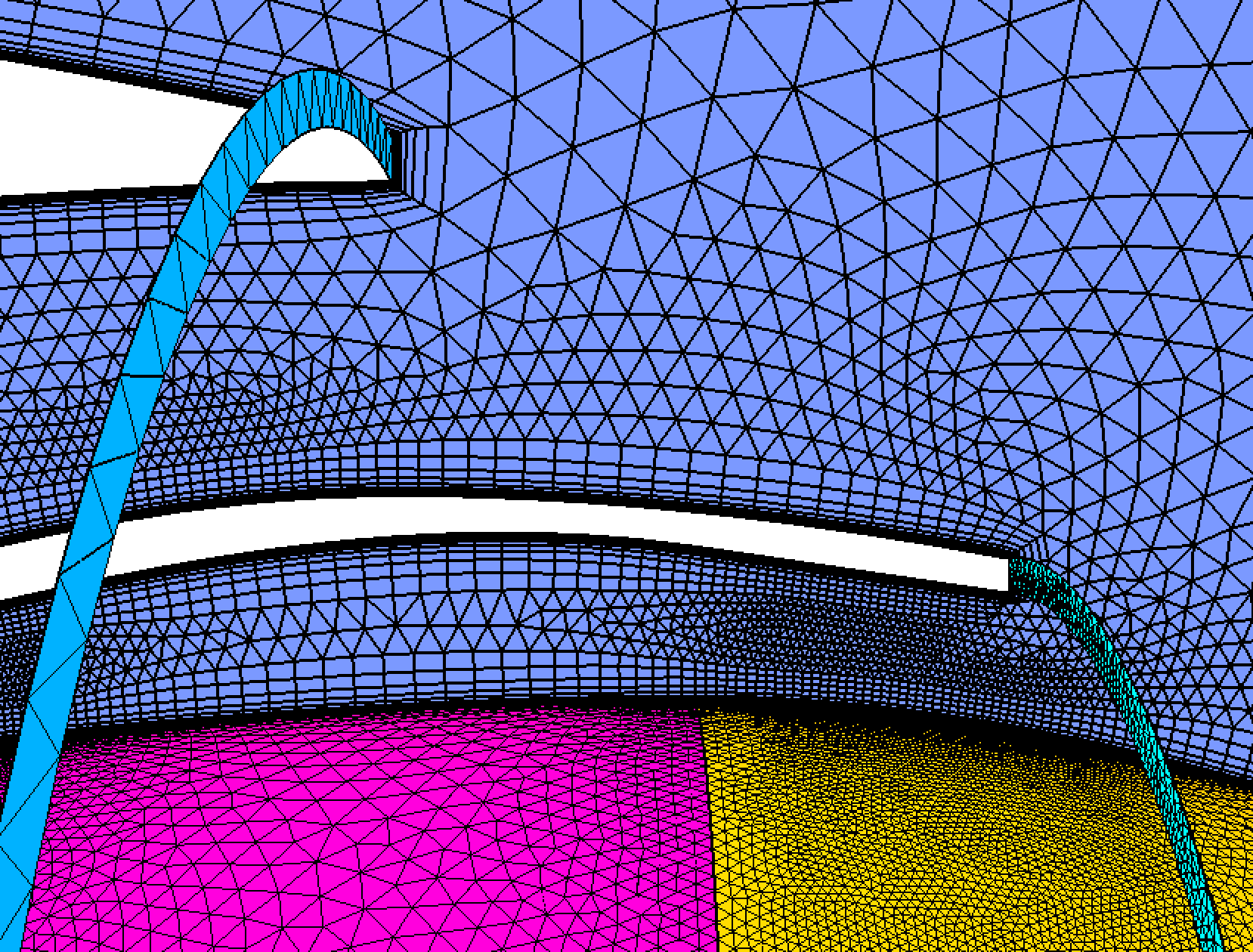
Engine nacelle with discrete geometry definition.
A jet engine nacelle in a farfield. Reference length is set equal to the engine
core diameter. Farfield
IDs are specified. BL thickness with minimal isotropic region thickness is also
specified. Proximity checking and spacing modification is automatically used in
the regions where the components are in close proximity.
aflr4 -i nacelle.surf -o nacelle_new.surf
-log -ff_ids 53-56 -ref_len
100 -Re_l 110e6
A compatible volume mesh can be generated using AFLR3. For
this case the proximity checking and spacing
modification process provides spacing sufficient to support BL generation
between nearby components.
aflr3 -i nacelle_engine_new -blc -y+ 1 -refx 100 -Re 110e6 -blrm 1.3 -nbldiff 2 -mblend 0 -log
A jet engine nacelle case with a
symmetry plane is also provided. Other than the geometry all other parameters
are the same.
aflr4 -i nacelle_engine_sym
-o nacelle_engine_sym_new.surf
-log -ff_ids 1,2 -int_ids
57, -ref_len 100 -Re_l
110e6
A compatible volume mesh can be generated using AFLR3. For
this case the proximity checking and spacing
modification process provides spacing sufficient to support BL generation
between nearby components.
aflr3 -i nacelle_engine_sym_new
-blc -y+ 1 -refx 100 -Re
110e6 -blrm 1.3 -nbldiff 2
-mblend 0 -log
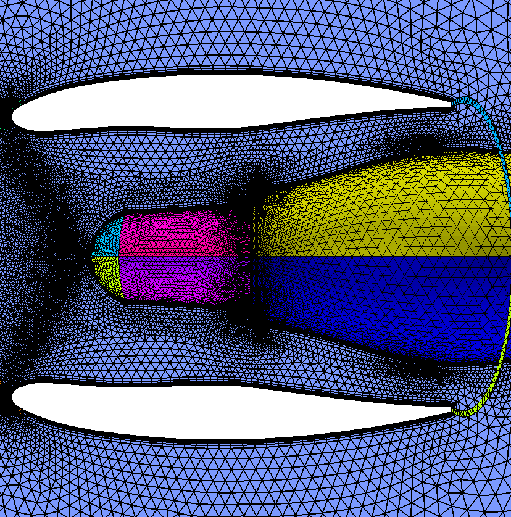
Rocket with discrete geometry definition.
A rocket in a farfield. Reference length is set equal to the mean rocket
diameter. Farfield
IDs are specified. BL thickness with minimal isotropic region thickness is also
specified. Without
and with edge refinement.
aflr4 -i rocket.surf -rocket_new.surf
-log -ff_ids 17-22 -int_ids
51,52 -ref_len 1.75
aflr4 -i rocket.surf
-rocket_new2.surf -log -ff_ids 17-22 -int_ids 51,52 -ref_len 1.75 -er_all
A compatible volume mesh can be generated using AFLR3.
aflr3 -i rocket_new
-blc -blds 0.0001 -log